
Overview
This tutorial involves wiring the H3LIS331DL accelerometer to the Raspberry Pi 0, as well as implementing the code in python that executes the readings. This specific accelerometer is 3-axis, meaning it records data in the x, y, and z-planes, and can take readings up to +-400g's. Once the sensor is wired to the pi, we had to code the pi to use the sensor, specifically GPIO pinouts.
Materials
- Raspberry Pi Zero
- H3LIS331DL accelerometer
- Headers to solder
- Connector wires
Authors
- Jarrod Huther and Katy Mocket
- Published Spring 2019
Process
Step 1: Solder header pins onto both the accelerometer and the pi (if not already attached).
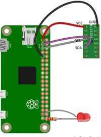
Step 2: Wire the Pi to the accelerometer as shown in the following diagram. IMPORTANT: The shape of the accelerometer is slightly different, but the pins still go to the corresponding ports (e.g., GROUND will still go to GPIO pin 9). Additionally, instead of VCC, connect to the 3.3v port on the accelerometer. Also ignore the LED, we will not be implementing it in our final product.
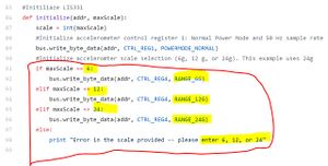
- Step 3: Code on Pi. Open up the Pi (either SSH or on a monitor) and use this link [1] to import code. Once a file with the code has been made, change the maxScale variable to 400, as well as every instance of 6, 12, and 24 to 100, 200, 400 (respectively). For example, if you see RANGE_6G = 0x00, change it to RANGE_100G = 0x00, and so on.
Testing the System
Once everything has been wired and properly coded, run the pi zero on either a monitor or via SSH. In the command line, type sudo python acc.py (or whatever file name you have chosen for code). You should begin seeing X, Y, and Z data updating in the command line, approximately 20 readings per second. Slowly rotate the pi zero so 1 g of force acts in each respective plane (the force of gravity). If all readings come back positive, the accelerometer is working and you may begin implementing it in your project.
Troubleshooting
- Make sure all wires are firmly connected, and no solder material has bled over onto other pieces of solder, as this could cause the pi to short out.
- In the X,Y, and Z readings, the accelerometer may record g's of magnitude slightly greater than 1 (e.g, 2, 3, or 4). This is okay, the system is still working, but output should be calibrated accordingly.
- Double-check that all values in source-code are changed to 100, 200, and 400g's where appropriate. Failing to do so could cause the pi to report false readings.
Source: Accelerometer + Pi Zero