
Overview
This lesson describes how to control both the speed and direction of a DC motor using Pythonand a L293D chip.
In Lesson 8, we used the Pi to generate pulses to control the position of a servo motor. In thislesson we use pulses to control the speed of a regular DC motor and the L293D motor controlchip to reverse the direction of the current through the motor and hence the direction in which itturns.
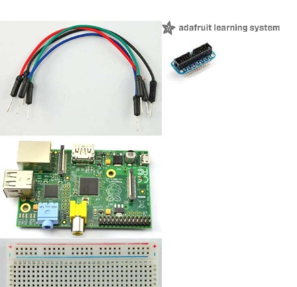
Parts
To build this project, you will need the following parts.
PWM
Pulse Width Modulation (or PWM) is a technique for controlling power. We use it here to controlthe amount of power going to the motor and hence how fast it spins. The diagram below shows the signal from the PWM pin of the Raspberry Pi.
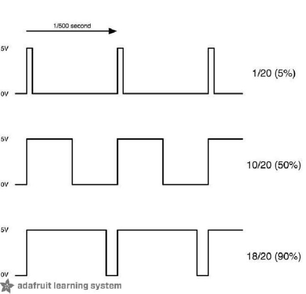
Every 1/500 of a second, the PWM output will produce a pulse. The length of this pulse controlsthe amount of energy that the motor gets. No pulse at all and the motor will not turn, a shortpulse and it will turn slowly. If the pulse is active for half the time, then the motor will receive half the power it would if the pulse stayed high until the next pulse came along.
The PWM Kernel Module
Adafruit and Sean Cross have created a kernal module that is included with theOccidentalis (http://adafru.it/aQx) distribution. For details of creating an Occidentalisfollow thislink (http://adafru.it/aWq). If you want to use the module with Raspbian or some otherdistribution, then there is help on installing the kernel module into your environmenthere (http://adafru.it/aQx). You used the PWM and Servo Kernel Module in Lesson 8, to control a Servo. This time, you willuse the same module to control the speed of the motor. The modules interface uses a file type of interface, where you control what the output pin andtherefore the servo is doing, by reading and writing to special files. This makes it really easy tointerface with in Python or other languages. The files involved in using the module to drive a servo are listed below. All the files can befound in the directory /sys/class/rpi-pwm/pwm0/
FileDescriptionactive
This will be 1 for active 0 for inactive. You can read it to find out if the output pin isactive or write it to make it active or inactive.delayedIf this is set to 1, then any changes that you make to the other files will have noeffect until you use the file above to make the output activemodeWrite to this file to set the mode of the pin to either pwm, servo or audio. Obviouslywe want it to be pwm. Note that the pin is also used by the Pi's audio output, so youcannot use sound at the same time as controlling a motor.frequencyThis is the number of pulses to be produced per second.duty The value here needs to be between 0 and 100 and represents the percentage of the pulse during which the power to the motor is on. The higher the number, thefaster the motor will spin.
L293D
This is a very useful chip. It can actually control two motors independently. We are just usinghalf the chip in this lesson, most of the pins on the right hand side of the chip are for controllinga second motor, but with the Raspberry Pi, we only have one PWM output.
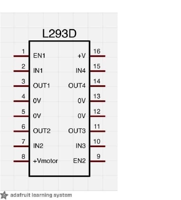
The L293D has two +V pins (8 and 16). The pin ‘+Vmotor (8) provides the power for themotors, and +V (16) for the chip's logic. We have connected pin 16 to the 5V pin of the Pi andpin 8 to a battery pack.
Hardware
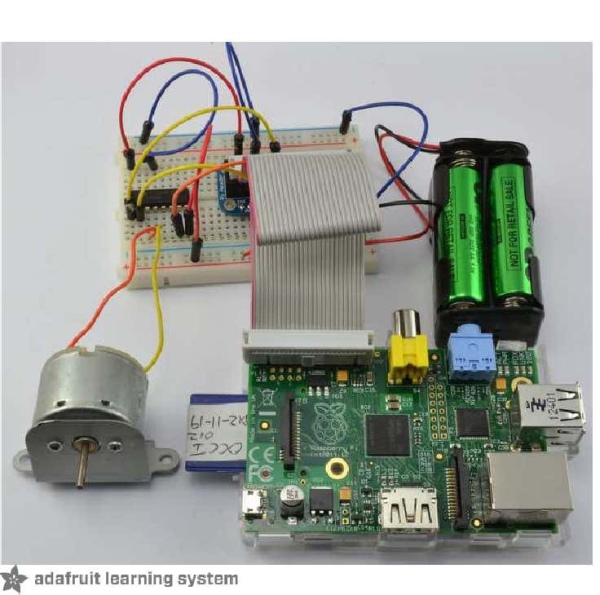
There are two reasons why we need to use a L293D chip in this project. The first is that theoutput of the Raspberry Pi is nowhere near strong enough to drive a motor directly and to trythis may damage your Raspberry Pi.Secondly, in this lesson, we want to control the direction of the motor as well as its speed. Thisis only possible by reversing the direction of the current through the motor, something that theL293D is designed to do, with the help of two control pins.
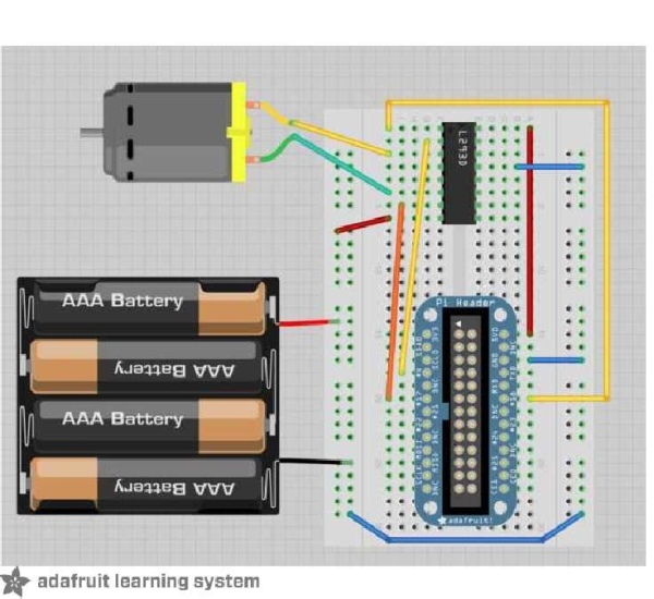
The project fits nicely on a half-sized breadboard.
Software
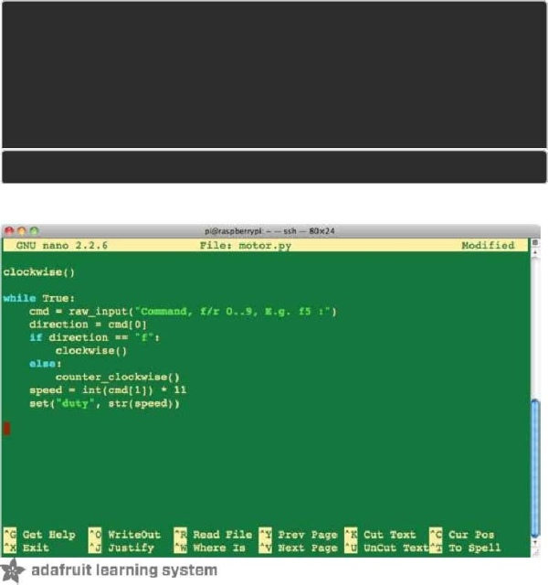
Since we need to control pins (connected to pin 4 and 17 of the GPIO) we also need to use theGPIO library. For details of this, seeLesson 4 (http://adafru.it/aTH). There are lots of ways to get the sketch from the listing below onto your Raspberry Pi. Perhapsthe easiest is to connect to your Pi using SSH (SeeLesson 6 (http://adafru.it/aWc)) opening aneditor using the command below:nano motor.pyand then pasting in the code below, before saving the files using CTRL-x.
Here is the code:
import RPi.GPIOas ioio.setmode(io.BCM)in1_pin =4in2_pin =17io.setup(in1_pin, io.OUT)io.setup(in2_pin, io.OUT)
def set(property, value): try: f = open(“/sys/class/rpi-pwm/pwm0/” + property,'w') f.write(value) f.close()except: print(“Error writing to: ” + property +” value: ” + value) set(“delayed”,”0″)set(“mode”,”pwm”)set(“frequency”,”500″)set(“active”,”1″)def clockwise(): io.output(in1_pin, True)io.output(in2_pin,False)def counter_clockwise(): io.output(in1_pin,False) io.output(in2_pin, True)clockwise()while True: cmd = raw_input(“Command, f/r 0..9, E.g. f5 :”) direction = cmd[0] if direction ==”f”: clockwise() else:counter_clockwise() speed =int(cmd[1]) *11 set(“duty”, str(speed))
he Python program first sets-up the two GPIO pins to be outputs. It then defines the sameconvenience function (“set”) that we used in Lesson 8, to write to the PWM Kernel Module. Thisis then used to set the parameters for PWM. There are two other functions defined, “clockwise” and “counter_clockwise”, that control thedirection of the motor by changing the two input pins.If both control pins are HIGH, or both LOW then the motor will be stopped. But if IN1 is HIGH andIN2 LOW it rotates in one direction, reversing in direction if the values of IN1 and IN2 arereversed. The main loop of the program waits for you to enter commands in the format of a letter (“f” or“r”) and a digit between 0 and 9. The letter sets the direction of the motor and the digit thespeed, by multiplying the digit by 11 to give a value between 0 and 99 that the PWM libraryexpects.
Test & Configure
To run the program, you will need to run it as super user to get access to the GPIO pins, sotype:sudo python motor.py You will then get a prompt for you to enter a command. Try entering a few 2 letter commandsas shown below.
$sudo python motor.py
Command, f/r0..9, E.g. f5 :f9
Command, f/r0..9, E.g. f5 :r4
Command, f/r0..9, E.g. f5 :
Source: Adafruit's Raspberry Pi Lesson 9. Controlling a DC Motor