This article deals with adding a push button on the Raspberry Pi’s GPIO pins and writing a daemon that handles push button events. If we press the push button for less than 2 seconds, we want the daemon to shutdown the system and if the push button is still depressed for 2 or more seconds, the daemon must restart the system. First we deal with the hardware part of the problem.
Things to know:
- Raspberry Pi has a 3.3 V microcontroller which means 3.3 V is considered logic high
- The GPIO pins do not have voltage/current protection, so working voltage must strictly be 3.3 V and current in individual pins must be less than 16 mA
Wiring up hardware
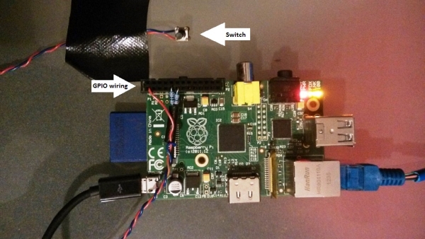
Before we can wire up the GPIO pins, we need to convert the male GPIO pins on the board to female. According to the internet, an IDE hard drive cable is a good candidate for this. Unfortunately, I couldn’t find this cable in my local electronics shop so I settled with the following connector.
I did have to bend the pins a little on the connector so that it grips the GPIO pin well. Scroll down to see how the connector fits on the GPIO pins.
If you are new to electronics, wiring up the 3.3 V source on the board directly to a GPIO pin and putting a switch between them seems to be a no brainer. Unfortunately, this has two problems. First, if an accidental short occurs, a source voltage directly connected to a pin can cause large surge of current – damaging the hardware. Raspberry Pi’s individual pin is rated to work with current less than about 16 mA. We want to keep the current well below this limit. To solve this problem, we add a resistance big enough to limit current.
Secondly, when the switch is open, the pin is in what’s called a floating state. This means that because the pin is connected to neither a voltage source or ground, the input pin is in an indeterminate state. During this project, I once incorrectly wired the circuit to leave the input pin as floating. When I pushed the button, the program would correctly read the pin value as high because it was tried to a 3.3 voltage source. When released though, the program would still read high. But if the program was asked to read the pin a second time, then the program would correctly read low. This strange behaviour is caused by a floating pin.

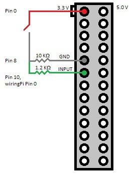
From the wiring diagram, we can see that when the switch is open, the input pin is connected to the ground. When switch is closed, the 3.3 V source is parallel to the 1.2 KΩ load which means input pin will be at 3.3 V (because the source is connected in parallel to both the loads). The 10 KΩ resistor is the pull-down resistor while 1.2 KΩ resistor is a current protection resistor. Using the consequence of Ohm’s law – Voltage = Resistance * Current – we can calculate that when Voltage = 3.3 V, using the resistance values used above gives us a current below the rated limit.
For more detail: Adding shutdown restart pushbutton for Raspberry Pi


