
The Raspberry Pi does not have any analog inputs, but that does not mean that you can't use some types of analog sensors. Using a couple of resistors and a capacitor, you can use a “step response” method to measure resistance. Which is just great if you are using a pot, photoresistor or thermistor.
The Recipe that follows is taken from my new book “The Raspberry Pi Cookbook”. This way of using sensors was inspired by this work from Adafruit.
To make this recipe, you will need:
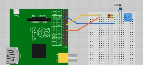
• Breadboard and jumper wires
• 10kΩ trimpot
• Two 1kΩ resistors
• 220 nF capacitor
Open an editor (nano or IDLE) and paste in the following code. As with all the program
examples in this book, you can also download the program from the Code section of
import RPi.GPIO as GPIO
import time
GPIO.setmode(GPIO.BCM)
a_pin = 18
b_pin = 23
def discharge():
GPIO.setup(a_pin, GPIO.IN)
GPIO.setup(b_pin, GPIO.OUT)
GPIO.output(b_pin, False)
time.sleep(0.005)
def charge_time():
GPIO.setup(b_pin, GPIO.IN)
GPIO.setup(a_pin, GPIO.OUT)
count = 0
GPIO.output(a_pin, True)
while not GPIO.input(b_pin):
count = count + 1
return count
def analog_read():
discharge()
return charge_time()
while True:
print(analog_read())
time.sleep(1)
When you run the program, you should see some output like this:
$ sudo python pot_step.py
10
12
10
10
16
23
43
53
67
72
86
105
123
143
170
The reading will vary between about 10 and about 170 as you rotate the knob of the
trimpot.
Discussion
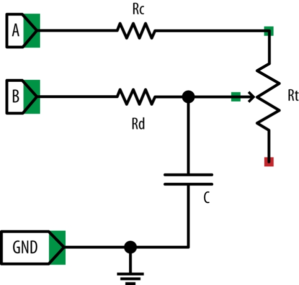
To explain how this program works, I first need to explain how the step response technique
can be used to measure the resistance of the variable resistor.
This way of doing things is called step response because it works by seeing how the circuit
responds from the step change when an output is switched from low to high.
You can think of a capacitor as a tank of electricity, and as it fills with charge, the voltage
across it increases. You can’t measure that voltage directly, because the Raspberry Pi
doesn’t have an ADC converter. However, you can time how long it takes for the capacitor
to fill with charge to the extent that it gets above the 1.65V or so that constitutes
a high digital input. The speed at which the capacitor fills with charge depends on the
value of the variable resistor (Rt). The lower the resistance, the faster the capacitor fills
with charge and the voltage rises.
For more detail: Analog Sensors without Analog Inputs on the Raspberry Pi