
Introduction
Driven by the need for
untethered mobility and
ease of use, many systems
rely on rechargable bat-
teries as their primary
power source. The battery
charging circuitry for th
ese systems is typically
implemented using a fixed-
function IC to control
the charging current/voltage profile.
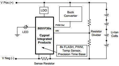
The C8051F30x family provides a flexible alterna-
tive to fixed-function batt
ery chargers. This appli-
cation note discusses how to use the C8051F30x
family in Li-Ion battery charger applications. The
Li-Ion charging algorithms ca
n be easily adapted to
other battery chemistrie
s, but an understanding of
other battery chemistries is required to ensure
proper charging for those chemistries.
The code accompanying this
application note was
originally written for C8051F30x devices. The
code can also be ported to
other devices
in the Sili-
con Labs microcontroller range.
Key Points
• On-chip high-speed, 8-bit ADC provides supe-
rior accuracy in monitoring charge voltage
(critical to prevent overcharging in Li-Ion
applications), maximizing charge effectiveness
and battery life.
• On-chip PWM provides means to implement
buck converter with a very small external
inductor.
• On-chip Temp sensor provides an accurate and
stable drive voltage for determining battery
temperature. An external RTD (resistive tem-
perature device) can also be used via the flexi-
ble analog input AMUX.
• A single C8051F30x platform provides full
product range for multi-chemistry chargers,
expediting time to market and reducing inven-
tory
Charging Basics
Batteries are exhaustively
characterized to deter-
mine safe yet time-efficie
nt charging profiles. The
optimum charging method fo
r a battery is depen-
dent on the battery’s ch
emistry (Li-Ion, NiMH,
NiCd, SLA, etc.). Howeve
r, most charging strate-
gies implement a 3-phase scheme:
1. Low-current conditioning phase
2. Constant-current phase
3. Constant-voltage phase/charge termination
All batteries are charged
by transferring electrical
energy into them (refer to the references at the end
of this note for a battery primer). The maximum
charge current for a batter
y is dependent on the bat-
tery’s rated capacity (C).
For example, a battery
with a cell capacity of 1000mAh is referred to as
being charged at 1C (1 tim
es the battery capacity) if
the charge current is
1000mA. A battery can be
charged at 1/50C (20 mA
) or lower if desired.
However, this is a common trickle-charge rate and
is not practical in fast charge schemes where short
charge-time is desired.
Most modern chargers
utilize both trickle-charge
and rated charge (also refe
rred to as bulk charge)
while charging a battery. The trickle-charge current
is usually used in the in
itial phases of charging to
minimize early self heati
ng which can lead to pre-
mature charge terminati
on. The bulk charge is usu-
ally used in the middle phase where the most of the
battery’s energy is restored.
During the final phase of battery charge, which
generally takes the majori
ty of the charge time,
either the current or vol
tage or a combination of
both are monitored to determine when charging is
complete. Again, the term
ination scheme depends
on the battery’s chemistry. For instance, most Lith-
ium Ion battery chargers hold the battery voltage
constant, and monitor for minimum current. NiCd
batteries use a rate of change in voltage or tempera-
ture to determine when to terminate.
Note that while charging a battery,
most
of the elec-
trical energy is stored in
a chemical process, but not
all
as no system is 100 percent efficient. Some of
the electrical energy is c
onverter to thermal energy,
heating up the battery. This is fine until the battery
reaches full charge at which time
all
the electrical
energy is converted to thermal energy. In this case,
if charging isn’t terminated, the battery can be
damaged or destroyed. Fast chargers (chargers that
charge batteries fully in
less than a couple hours)
compound this issue, as these chargers use a high
charge current to minimize
charge time. As one can
see, monitoring a battery’s temperature is critical
(especially for Li-Ion as
they explode if over-
charged). Therefore, the
temperature is monitored
during all phases. Charge
is terminated immedi-
ately if the temperature rises out of range.
Li-Ion Battery Charger –
Hardware
Currently, Li-Ion batteries
are the battery chemistry
of choice for most applic
ations due to their high
energy/space and energy/weight characteristics
when compared to other
chemistries. Most modern
Li-Ion chargers use the ta
pered charge termination,
minimum current (see Figur
e 2), method to ensure
the battery is fully char
ged as does the example
code provided at the end of this note.
The most economical way to
create a tapered ter-
mination charger is to us
e a buck converter. A buck
converter is a switching
regulator that uses an
inductor and/or a transf
ormer (if isolation is
desired), as an energy storage element to transfer
energy from the input to
the output in discrete
packets (for our example
we use an inductor; the
capacitor in Figure 3 is used for ripple reduction).
Feedback circuitry regulates the energy transfer via
the transistor, also referred
to as the pass switch, to
maintain a constant voltage or constant current
within the load limits of the circuit. See Figure 3
for details.
Tapered Charger Using the F30x
Figure 3 illustrates an
example buck converter
using the ‘F30x. The pass sw
itch is controlled via
the on-chip 8-bit PWM (Pulse Width Modulator)
output of the PCA. When the switch is on, current
will flow like in Fi
gure 3A. The capacitor is
charged from the input through the inductor. The
inductor is also charged. When the switch is
opened (Figure 3B), the induc
tor will try to main-
tain its current flow by inducing a voltage as the
current through an inductor
can’t change instanta-
neously. The current then flows through the diode
and the inductor charges
the capacitor. Then the
cycle repeats itself. On a
larger scale, if the duty
cycle is decreased (shorter
“on” time), the average
voltage decreases and vice
versa. Therefore, con-
trolling the duty cycles al
lows one to regulate the
voltage or the current to within desired limits.
Selecting the Buck Converter Inductor
To size the inductor in th
e buck converter, one first
assumes a 50 percent duty cy
cle, as this is where
the converter operates most efficiently.
Duty cycle is given by E quation 1, where T is the period of the PWM (in our example T = 10.5 S).Charge Current Charge Voltage Time
Conditioning
Phase
Current regulation Voltage regulation
Figure 2. Lithium I
on Charge Profile.
Inductor
Capacitor
Power
Source
Battery
Inductor
Pass Switch Off
Capacitor
Power
Source
Battery
(A)
(B)
Pass Switch On
Shottky
Diode
Shottky
Diode
Figure 3. Buck Converter.
DutyCycle
ton t Equation 1. Duty Cycle.
For more detail: App note: Lithium ion battery charger using C8051F300