
Step 1: Arduino IDE and Library Setup
The advent of the Arduino put power into the hands of the same type of folks who originally designed the first blue boxes. We can write our own micro-controller code, use easily obtainable Radio Shack parts to design unique hardware and much, much more. There are many ways we can design our blue boxes and this article will only cover a simple few of them.
Tone Library
First is the Tone library – square wave – synthesis device. This device can be made using the Arduino Micro ATMega32u4 based chip with the Arduino (external) Tone library. The library needs to be modified to work with the ATMega32u4 chip and a modified version can be downloaded on my website here. This library and chip have only been tested with the Arduino IDE version 1.0.5 Now that we have the library and chip, we now need a simple schematic that we can use with a keypad.
Keypad Library
The Arduino Keypad library can be found here. All libraries need to be in the Arduino “libraries” directory located in the base of your IDE installation. e.g. C:\Users\trevelyn412\Documents\Arduino\libraries Most of the time this is as simple as extracting the library from a zip file, but check your library's documentation if advanced instructions for installation are required.
TMRpcm Library
Finally, the TMRpcm library is used by schematic 2 for playing WAV files from our second blue box. The author of this library was kind enough to help me via email as I was having difficulty with the non-existent SeeedStudio v3 SD card Shield documentation. It plays mono files at 32khz and below (I use 22khz) at 8 bit. There are however a lot of advanced functions and code optimizations that we can do by editing the pcmConfig.h header file, such as allowing a larger buffer space as we uncomment and change the line,
#define buffSize 128 //must be an even number
Also, by storing a single frequency WAV file onto the SD card, we need to lower it's actual cycles by 25. This means in Audacity, generate a tone for 2575hz rather than 2600 for supervisory signalling.
The sounds I have created are all in the directory “sounds” located at the root of the micro SD card. There are several notes by the Arduino community for storing files and accessing them via Arduino libraries located here. These are very important to follow by.
Hardware Required
In these tutorials I use the following parts,
- Simple 10k Ohm resistors
- Momentary push-buttons
- LED lit toggle power switches
- Arduino UNO && Arduino Micro
- SeeedStudio v3 SD Card Shield
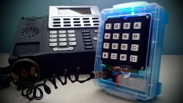
- BLUE Advantus Super Stacker Crayon Boxes
- Blue LEDs
- 100k Potentiometers for volume
- 2.2uF non-polarized capacitor (optional)
- 9V batteries (one schematic uses 2 in parallel
- Rotary dial mechanism from old phone
- Velleman 4×4 keypad
- 150 Ohm telephone receiver speaker part #SD150(ph) (for optimal output)
And anything else is optional. The LEDs are optional and hardware with LEDs like the power switches are also optional. Changing the schematic for accommodate for these should be very easy.
Arduino Experience
This tutorial assumes very basic knowledge of the code used by the Arduino and how to set up a basic project using a bread board. I do, however go into instructions on how to manage these projects into boxes of their own, but that requires soldering and solder experience, in most cases.
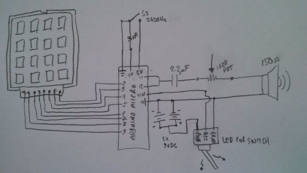
Step 2: 1st Schematic
I will be showing you how to construct the two boxes that I have personally made using the Tone synthesis library and the Arduino UNO / SeeedStudio SD Shield – TMRpcm WAV file player versions. For two of these tutorials I will be using the Velleman 4×4 keypad. This is a very study keypad which comes with a pin-out diagram on the back of the package for easily hooking it up to the Ardiuno.
In the image above is the simplest schematic in this series. It uses only a 4×4 keypad, a single supervisory signalling button, a volume knob (potentiometer), and a stylish LED-lit power button. The momentary pushbutton requires the pin 10 also have a 10k Ohm resistance to ground. The other side of the switch goes directly to the 5V pin as we can see form the simple schematic. Developing this hardware layout is simple, but debugging can take hours. It's best to use a simple bread-board for those unfamiliar with schematic diagrams or electronics.
Step 3: Code for Schematic 1
Programming
The code for this new schematic in it's entirety can be found here on my pastebin.com profile. For the sake of this tutorial we will cover most of the key concepts of the syntax I have used. First of all the Arduino uses a programming language which is object-oriented; C++. This language is quite powerful and powers a lot of modern-day web site logic, micro-controllers, and much more!
Keypad
First we create a two dimensional array of integers that we use for holding the frequencies as specified per digit by the Wikipedia Blue Box page. We also set a duration as a typedef unsigned integer array. These integers are playback duration periods.
int bb[16][2] = { // MF 0,1,2,3,4,5,6,7,8,9,kp,st,2400+2600,kp2,st2,ss4 super<br>  {1300,1500},{700,900},{700,1100},      // 0,1,2
  {900,1100},{700,1300},{900,1300},      // 3,4,5
  {1100,1300},{700,1500},{900,1500},     // 6,7,8
  {1100,1500},{1100,1700},{1500,1700},   // 9,kp,st
  {2600,2400},{1300,1700},{900,1700},    // 2400+2600,kp2,st2
  {2400,2040},                           // ss4 Supervisory
};
<p>uint8_t bbdur[2] = {60,100};</p>
Next, we create an array matrix of keys as characters. These characters will be used each time a button on the keypad is pressed. We also set the rows and pins integer arrays.
char keys[4][4] = {<br>  {'1','2','3','a'},
  {'4','5','6','b'},
  {'7','8','9','c'},
  {'#','0','*','d'}
};
<p>byte rowPins[4] = {5,4,3,2}; //connect to the row pinouts of the keypad<br>byte colPins[4] = {9,8,7,6}; //connect to the column pinouts of the keypad</p>
Next we create a keypad object and a simple array of Tone objects. Since we are playing tones out of two pins at once, this just makes our lives simpler when writing and debugging the code.
Tone freq[2]; // array of Tone objects, now we can play as freq[0].play(); etc<br>Keypad keypad = Keypad(makeKeymap(keys),rowPins,colPins,4,4);
Reading Buttons and Playing Tones
In the setup() function, we need to set the freq[0] and freq[1] pins for output. This is simple. We also set the “pin mode” for the 2600 button and set an event-listener, which is a procButton() button processing custom function call. This is event-driven programming. This basically means that we “listen” for keys to be pressed, which would be an “event.” The main loop() function is what handles the events and listeners for us.
freq[0].begin(11); // Initialize our first tone generator<br>freq[1].begin(12); // Initialize our second tone generator
pinMode(10, INPUT); // 2600 button
keypad.addEventListener(procButton);
We have kept our main loop() method simple, which is good since it is constantly being called. The first line,
char button = keypad.getKey();
basically calls the getKey() method of the keypad object to see if and which key was pressed. The code,
if(digitalRead(10)==HIGH){ // play 2600Hz if top button pressed<br>  super(); // supervisory signalling
}
simply listens for voltage on pin 10 and if found, plays the 2600hz frequency by calling the custom supervisory signalling super() function. This is the very first function defined just below the loop() function. It is also the first function to call the custom single frequency playing sf() function as,
sf(2600,750);
The arguments we pass to this function are the frequency to be played, and the duration. After lexically assigning the frequency and duration to integer variables of the same names, the custom sf() function only calls a single play method on a single pin as,
freq[0].play(frequency,duration);
This is our first look at the tone synthesis play method from the Tone library. So, if you can imagine playing two tones, for multi-frequency would look similar, but with two pins, as,
freq[0].play(frequency,duration);<br>freq[0].play(frequency,duration);
And that is exactly what the custom multi-frequency playing mf() function does.
So how do we process each key press in the procButton() function? Using a case-switch logic. The constants “RELEASED,” “PRESSED,” and “HOLD,” (not “HELD” for some strange reason), are part of the keypad library and we can use the in a case-switch logic block as,
switch (keypad.getState()){<br>case RELEASED: // drop right away
  // do some stuff
  break;
case PRESSED: // momentary
  // do some stuff
  break;
case HOLD: // HELD (special functions)
  // do some stuff
  break;
}
And that's exactly what we do. Since the procButton() function is an event-handler called by the loop() function, we get a keypadevent object passed to it's handler procButton(). This object can be treated as a simple character – and we do that by simple subtracting the integer 48 from it to obtain which key was pressed from 0-9.
void procButton(KeypadEvent b){<br> b -= 48;
Now we know which key was pressed and pass it to the mf() function which uses the multidimensional array bb[] which we created earlier to play the mf tones. You may have noticed that the KP (*) and ST (#) are not 0-9. This is correct, as they come through and after the subtraction are -13 and -6 respectively. The mf() function then handles these as,
}else if(digit==-13){<br>  digit = 12;  // *
}else if(digit==-6){
  digit = 14;  // #
This then plays the tones as they are assigned in the bb[] multi-dimensional array.
We have now covered all of the key concepts programmatically with this schematic (1), let's move onto the second schematic and how we can play WAV files which offer a completely different sound to our blue boxes.
Extra Features
This code provides a massive amount of extra features including recording digits into and array for playback, and different modes of operation. The code is very straight forward Arduino C++ code. Long press ‘A‘ to cycle through the different modes. Each time we change modes the notifyMode() function will pulse out a code of 440hz beeps to let us know which mode we are currently using. All modes are fully described on my weblog here or on the Wikipedia page for blue box specifications.
Step 4: Schematic 2
This schematic involves the use of the SeeedStudio SD card shield for the Arduino UNO. I am using the discontinued v3 Shield from SeeedStudio. The on-board toggle switch is to switch back and forth between the micro-SD slot and the standard SD slot.
The schematic shows a multi-colored LED being used, simply because I didn't have an extra single Blue LED laying around. Everything else is seemingly the same as the previous version (schematic 1).
This device is actually a lot simpler than the first as far as the code goes – but a lot more advanced as well. The reason being is that it is very easy to run out of memory with the Arduino UNO, and there seem to be a lot of bugs. So the only concept we will be covering is how to play the WAV files and a few caveats of storing playable WAV files on your Micro SD card.
Pin 9 is used by the TMRpcm library for playing back tones, so this interrupts our sequential 2-9 keypad pin layout. Also pins 10-13 are being used by the SD card shield which leaves us with no extra pins to finish our button and last keypad pins on the right side of the board. No worries, we can use the Analogue input pins on the left side (as you can see from our schematic 2 in the image above).
Step 5: Code for Schematic 2
Programming
The code differences are not very hefty for this version. The complete code-listing is available on my pastebin.com profile here. We should, however also cover how to record the WAV files which we will do below the code analysis section. We are, in fact using a different micro-controller board – the Arduino UNO and should make the changes to specify for it in the IDE.
Three new pre-processor directives are used,
#include  // preprocessor directives (header files)<br>#define SDPIN 10    // SD Card Pin for SeeedStudio SD Card Shield
#include  // to play WAV files
In the setup() function we use the code,
if (!SD.begin(SDPIN)) {<br>  Serial.println("initialization failed!");
}else{
  Serial.println("initialization success!");

}
tmrpcm.speakerPin = 9; //11 on Mega, 9 on Uno, Nano, etc
tmrpcm.setVolume(3); // set volume here (test for distortion)
To initialize the SD card by mounting it's file system, set the speaker output pin used by the TMRpcm object as 9, and also to set the volume programmatically. Setting the volume programmatically can also be done by using a simple button listener of for a keypad callback, but I left this up to the potentiometer as the software defined volume seemed to add a bit of distortion to the tones.
We create a simple TMRpcm object as,
TMRpcm tmrpcm; // create sound playing object
Then, we can now call the play() method and pass to it a character array, as,
tmrpcm.play("sounds/blusin01.wav");
And that's it.
Notes on File Names
The naming conventions especially! I chose to stick with a simple 8 character limit for every file. for example 0-9 MF tones,
- blusin00.wav
- blusin01.wav
- blusin02.wav
- blusin03.wav
- blusin04.wav
- blusin05.wav
- blusin06.wav
- blusin07.wav
- blusin08.wav
- blusin09.wav
This ensured good compatibility and should be followed at least for the purposes of this documentation.
File Creation with Audacity
I used Audacity to create all of my sound files. When you first open audacity at the bottom left side of the screen you can change the frequency to 22khz from the default 44khz. Then got to “Generate->Tone” and select 700 as the frequency. I use an amplitude of 0.5 which works well with low distortion. Click the right down arrow and select the only option with “milliseconds” and then set the value to, 00.00.00.066 which is 66 milliseconds.
Next, click anywhere in the grey area outside of the tone clip and repeat the process but choose 900hz. This will create another mono channel tone just below the first as seen in the screenshot above. Now click “File->Export” and save it as “Other Uncompressed Files.” Click on the “options” dialog and select “unsigned 8bit Microsoft PCM.”
Save it to the sounds directory of the SD card and it should now be playable by the Arduino code.
For more detail: Arduino-Based Blue Box (Phone Phreaking)