
With my new toy Raspberry pi I've done several testing projects from
instructables, adafruit etc. But after a while it became boring and I've started looking for something actually useful for me. My previous playground was my new phone several weeks ago which came with new feature NFC reading. Thought and thought together gave me idea for attendance system for our small (family) company using NFC tags. The additional kick was my interest in those systems before, but discovering the cheapest are for around $750 I decided it is too much for such small company as 6 employees.
As I don't have any experience with “mature” attendance systems, I've decided only to implement basic features. These consist of logging incoming people, outcoming people, start and end of a break and deleting last inserted action (in case of mistype during logging).
All these actions are logged into local MySQL database from where I can display it and manipulate with my front-end application. Because the SD card is not such safe data medium, especially when loosing power unexpectedly, I'm uploading all data daily to my local server, where I keep backup in case of corruption of the SD card.
During normal operation of the logging station, display shows current date and time and calls for action selection. When you choose appropriate action on the keyboard, display shows selected action and calls for attaching the TAG to the reader. Also the LED under display also turns on.
When the TAG is read, the LED turns off and beep signal comes out the speaker. For a brief moment display shows action and name of the owner of the card. Then everything returns to the default state waiting for another entrance.
For foot notice, this whole project including source codes is licensed under Beer-ware licence as follows:
Jakub Dvorak wrote this file. As long as you retain this notice you can do whatever you want with this stuff. If we meet some day, and you think this stuff is worth it, you can buy me a beer in return.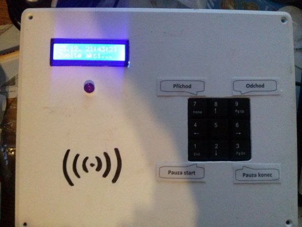
Step 1: Materials list
Everything you need for this project can be bought on E-Bay or in many Chinese e-shops like dealextreme etc.
For this project you'll need following items:
- Raspberry Pi model B
- 16×2 display
- Mifare RFID Reader
- USB numeric keypad
- LED diode holder
- Red LED diode
- Active 3V buzzer
- Small breadboard and various F-F and M-F jumper cables
- Box
- Various screws and/or glue gun, LED resistor, display 10k potentiometer
I recommend Raspberry Pi model B, because of the integrated LAN and two USB ports. That way you can use either LAN+USB keyboard or USB keyboard and USB WiFi dongle.
You can use any display, but I used HD44780 (the same display as found on adafruit), because it has well documented usage and uses only few pins from Raspberry.
I've chosen 13.56 MHz RFID reader and tags, because I've already got few tags with this technology from my experimenting with my cellphone. I've also found good How To (http://fuenteabierta.teubi.co/2013/07/utilizando-el-lector-nfc-rc522-en-la.html) and with a little help of Google translator modified given source to my needs.
Any numeric keypad can be used. Those with high buttons might be better due to thickness of the box. For installation just remove any extra buttons with small knife or screwdriver.
LED and LED holder are pure extra which are not needed for the device to be operational, but are good as extra indicator of actions.
The same is with the buzzer. I felt such a device should have it's own voice for letting people know it is working.
Breadboard and jumpers are for interconnection between each device because several pins (3.3V, GND,…) are used for more than one part. You can of course use soldered board, but I wanted to be able to replace each part easily and just glued it together with glue gun.
You'll also need few screws and/or glue gun for attaching all the pieces together. For LED you'll need small resistor. For my red LED I've used 68 ohm one which should limit current to around 19 mA. Depending on your LED you can calculate value for the resistor for example on this address. Maximum GPIO current is discussed on several forums but I wouldn't go over 20mA. Potentiometer is for contrast adjustment of the display.
Step 2: Wiring it together
On the picture from Fritzing above you can see connections between each element. You can find the fzz file as download link down the page.
For troubleshooting of display connection you can refer to nice manual on adafruit website.
Connection is pretty straightforward so there shouldn't be any trouble.
I've cut holes in the lid of the box for display, LED and keypad, NFC reader remains under the lid for safety and it has strong enough signal to read tags through the plastic.
I used glue gun for the alignments in the box and it holds every component firm enough. And after testing even the wires are glued to the connectors to prevent accidental disconnecting during operation.
Also don't forget to drill holes for power and network cable (or just one hole, if you use WiFi dongle or PoE).
As final touch, mark spot on the outside of the lid where NFC reader is for easier reading.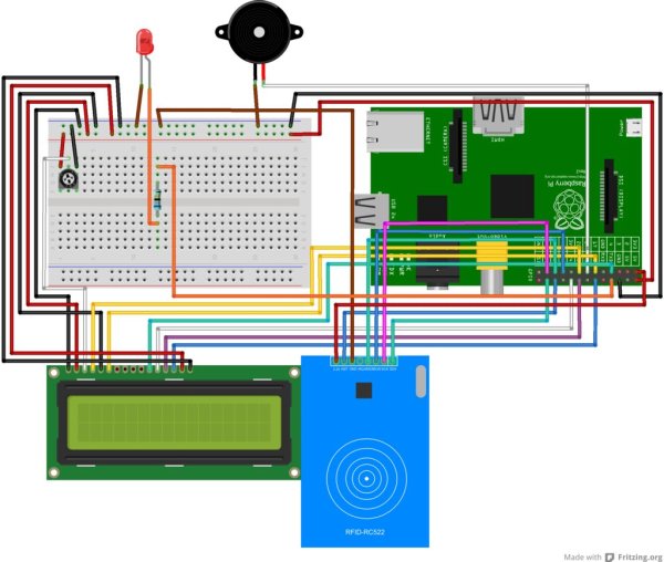
Step 3: The software
The software for this project is mixed from several tutorials and HOWTOs so there might be some leftovers from that, but it works for the time being and I might will fix that later (AKA never 😉 )
First of all you need default Raspbian image installed on your raspberry (LINK and HowTo).
After that we need few adjustments to enable correct function:
First of all we install files needed by the NFC reader as follows on previously mentioned page (http://fuenteabierta.teubi.co/2013/07/utilizando-el-lector-nfc-rc522-en-la.html)
1. Enable SPI device by editing file /etc/modprobe.d/raspi-blacklist.conf and comment the line blacklist spi-bcm2708 so it will read as follows:
# blacklist spi and i2c by default (many users don't need them)
# blacklist spi-bcm2708
blacklist i2c-bcm2708
2. Then download SPI-Py package to enable SPI communication for Python
git clone https://github.com/lthiery/SPI-Py
and install it via
sudo python setup.py install
We will also need the MFRC522 package from https://github.com/mxgxw/MFRC522-python but I had to edit it a little bit, so it's already in the source folder of this project.
The last think to get it work is installing GPIO for Python (if you wish, update the number in package version to the newest one):
wget https://pypi.python.org/packages/source/R/RPi.GPIO-0.5.4.tar.gz
tar zxf RPi.GPIO-0.5.4.tar.gz
cd RPi.GPIO-0.5.4
sudo python setup.py install
After that we can download the source code for this project
git clone https://github.com/Yimbo/attendance
Create table in your MySQL Database and upload structure to that database from file mysql.sql.
Next update file mysql.py according to your settings (server, username, password and database name).
For more detail: Attendance system using Raspberry Pi and NFC Tag reader