
Acknowledgement

The IPFW General Motors senior design team would like to give special thanks to Dr. Zhuming Bi,
and Yanfei Liu for their guidance throughout the build process. Their input was instrumental in
providing us with the right tools to make thorough design choices. We would like to thank the
IPFW engineering department professors who offered their time and constructive criticism
during our build process.
The Senior Design team also would like to thank Mr. John Mitchell and Mr. Jason Moyer for their
supervision during the use of the IPFW machine shop. Their expertise was appreciated during
the design and fabrication when exploring different mounting solutions and bracketry.
In addition, the team would like to thank Dr. Hosni Abu-Mulaweh and Dr. Hossein Oloomi for
providing us with the opportunity to showcase our talents, as well as giving us the chance to
refine our designs in the engineering perspective.
We would also like to thank our GM point of contact Tammy Keith for her support, and constant
updates when acquiring the build components of the prototype. Lastly, the senior design team
would like to thank our sponsor, General Motors Fort Wayne Assembly, for giving us an
opportunity to showcase our talents. Without their dedication and support, this would not have
been possible.
Abstract / Summary
This report contains the build process of both mechanical components and electrical components
followed by the testing and evaluations. The system is created from the bill of materials as listed
in Report 1. The system required additional features such as magnet carriage to deal with the
angles of certain spacers. A truss support was added to insure the integrity of the structure. A
multitude of panels and mounts were added to properly connect all component of the system.
The system is tested and evaluated on 8 different criterions based off the scope of the project
and goals desired by GM. The tests ranged from subjects such as the timing, failure reports,
different spacer positions, and more. The results of all 8 tests either meet or exceed the required
goal. In the required test 1 (R1), the system must be able to automatically move the magnet and
pick up the spacer regardless of type, and place it in a desired location. This operation has a
success rate of over 98%. The tests were performed continuously and can be determined as a
successful prototype.
The budget was kept under the limit of $15,000. The team only spent about 86% of the budget.
With the nature of the build, spare stock parts remains as possible repair and replacement items.
A list of suggestions and recommendations to create a better system is described. Changes to the
structure to allow more stability to the X actuator may be implemented to reduce the deflection
of the electric slide. The wrist attachment for the magnet could be improved in several ways such
as stronger material and different limiting straps such as a spring. The pneumatic system could
be improved by air resistor, to slow certain movements in the rare loss of power cases.
Section I: Building Process
Revisions and Additional Features
There were several revisions and additional features added to the original chosen design concept.
These revisions were added to increase functionality, stability, and ease of operation for the
prototype. These upgrades are detailed in the list below.
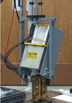
● Magnet carriage
○ Three of the spacers to be pulled are design to match slopes in the frame.
Due to this fact, the magnet cannot be rigidly mounted to the pneumatic actuator.
A wrist was designed to accommodate the motion necessary for the magnet’s
bottom face to be flush with the top of the spacer. This project is the first step in
creating an automated machine to cycle every 53 seconds. To ensure machine life,
the wrist carriage was design with stresses for infinite fatigue life with the project’s
safety factor of two. Stress equation development is located in Appendix A. The
final product is shown in the following Figure 1:
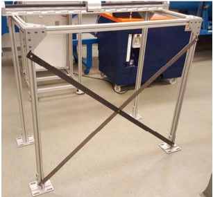
● Truss style support straps
○ In order to mitigate lateral sway in the frame when it is subjected to the
thrust of a heavy hanging load from the horizontal actuator; two 1 ½” X 56” steel
support straps were incorporated to increase the stiffness of the structure. This
truss style support is commonly used in many homebuilding and manufacturing
style framing applications for its ability maintain frame rigidity.
● Bracketry and Mounting plates
○ Thruster mounting bracket – In order to provide the system with the
desired flat horizontal actuator orientation as seen in Figure 1Figure 3, as opposed
to a side mount orientation), a bracket was needed to mount the horizontal
actuator to the vertical thruster. This decision was made as not to exceed side
load specifications for the horizontal actuator.
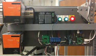
○ Electronic mounting plate – In order to provide a simulated “electrical
panel” to furnish ease of access for maintenance personnel that would commonly
be seen in production; a mounting plate was used to house electrical components.
This mounting plate keeps all components close, keeps the wiring safe to avoid
crimps, and keeps components orderly to provide for easy troubleshooting should
the future need arise.
○ Pneumatic mounting plate – Much like the electrical mounting plate, the
pneumatic mounting plate provides the components with concise organized home
that could easily be used to simulate a locking panel only accessed by cleared
employees to include maintenance.
● Mounting Base – The mounting base was modified to include added height for
bottom pin clearance and an adjustable simulated chassis with X & Y axis variation. The
X & Y axis variation was needed to simulate the normal fork truck loading conditions that
commonly occur in production. This variation occurs when frames are not loaded onto
the incoming buffer conveyor in the exact same spot every time. The simulated X & Y axis
variation ensures that the footprint of the magnet can account for these loading
conditions.
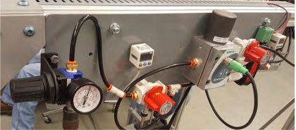
● Pneumatics
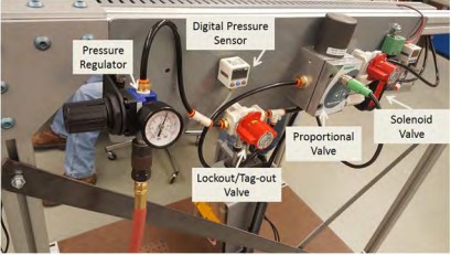
As discussed in the previous report, two components are pneumatic driven. The magnet is
actuated between two states (on and off). Finer control is necessary for the pneumatic actuator
as motion of the carriage is controlled between the full up and full down positions. The diagram
for the controls is displayed in Figure 8.
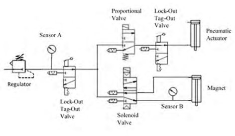
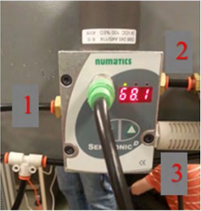
Regulator
A typical pneumatic regulator shown in Figure 9 is used to set the mainline pressure.
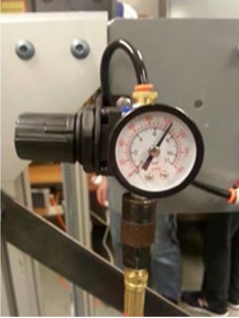
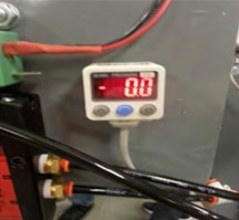
Sensor A
Sensor A shown in Figure 10 is used to monitor the mainline pressure set by the regulator. This
information is sent out as a signal that the Arduino can read.
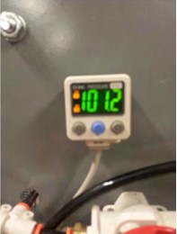
Sensor B
Sensor B is shown in Figure 11. This is a visual indicator for the current state of the magnet. If the
pressure at Sensor B matches the pressure at Sensor A, the magnet is currently on. If the two
sensor’s values differ, the magnet is off.
Lock-out Valves
Lock-out Valves are position to release pressure in the lines to the pneumatic components. The
first (Figure 12) was placed on the mainline to depressurize the mainline and magnet. The magnet
is depressurize since the solenoid valve allows backflow and the other size is vented to
atmosphere.
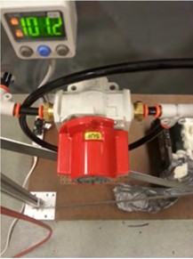
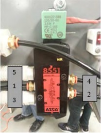
Proportional Valve
The vertical motion of the pneumatic cylinder is controlled through its acceleration. Acceleration
is caused by the net force of the tooling weight and force by the pneumatic cylinder. For the
prototype, the cylinder is being operated as a single action cylinder. Pressure is only supplied to
the bottom side of the piston. To control pressure within the cylinder, a proportional valve in
Figure 13 was chosen. The proportional valve sets the output pressure in Port 2 to a percentage
of the input pressure in Port 1. This percentage is determined by a control signal ranging from 0
volts to 10 volts. This signal is determined by two arrays in the code. The three arrays define
signal values for the Arduino to output every 0.1 seconds. Two arrays set the pressure curve for
the up stroke for loaded and unloaded conditions and the other sets the pressure curve for the
down stroke.
Solenoid Valve
The solenoid valve (Figure 14) has two positions. The position is set by either powering or
depowering the coil. The first position is its position when the coil is unpowered. In this position,
pressurized air is supplied through Port 4, while Port 2 is exhausted. The second position is the
result of the coil being powered. This position supplies pressurized air to Port 2 and exhausts Port
- Port 4 is connected to the bottom of the magnet’s cylinder and Port 4 to the top. By having the
solenoid valve connected in this manner, the magnet will stay on after a power loss until the
Arduino powers the coil.
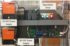
• Step Motor Drive and 48 VDC Power Supply
An additional power supply and new driver were added to control the 48VDC
stepper motor.
Build Guide
This section contains the detailed set of steps in creating the prototype system. Materials and
items are from the bill of materials listed and revision section. The usage of tools, both for steel
work and wood working is required. All steps are performed with safety considerations applied.
Safety applications vary from task to task, involving items such as safety glasses, gloves, and
hearing protection. Users are wearing personal protective equipment (PPE), while conducting
actions in proper work environments such as labs, and workshops.
Step 1 – Structure Creation
Fasten the 40x40mm aluminum rods to create a structure with the dimensions of 4’x4’x2’ as
shown in the Figure 16 below. Attach the corner brackets to each corner, and fasten them
together by the provided bolts and carriage nuts. Place the feet on the structure and using the
same bolts as provided earlier. These are screwed in by a metric Allen wrench.
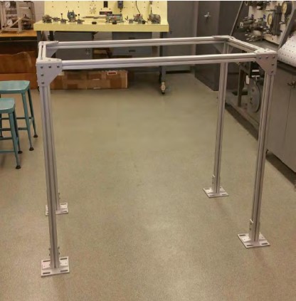
Take the two of the 2” x 5’-6” and create a “X” shape on the back side of the frame structure.
These metal straps are to help support the structure from deformation as the system is in action.
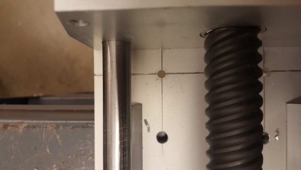
Step 2 – X Actuator
Mounting the Bimba Electric slide to the top side of the frame requires pre-drilling. To fit the
actuator to the top of the structure, the pre-existing holes only aligns two of the four holes. In
order to efficiently mount the actuator, use the pre-existing holes and then drill out two new
holes to the opposite end as shown below in Figure 17.
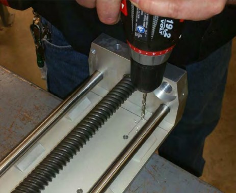
Carefully measure out the distance and drill accordingly. When the holes are finished, add four
carriage bolts and nuts provided by the structure to attach the actuator. These holes just need to
be large enough for the carriage bolts which have a diameter of .5”. They are not threaded in to
the actuator as seen in Figure 18.
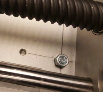
They are tightened by four nuts. These nuts need to be tighten equally for best results. A closer
image of this attachment is shown in Figure 19.
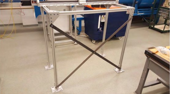
Step 3 – Truss Style Support Straps
Steel support straps are connected to the back side of frame. These 5’ 6” steel straps have holes
drilled at both ends and at the center. They are mounted to the frame in a “X” formation as
shown in Figure 20. The addition of these straps creates more rigid structure through increased
stiffness. It is important to note that edges of the straps were indexed to create a less hazardous
exposed edge. These indexed edges now lay flush with the frame as shown in Figure 20.
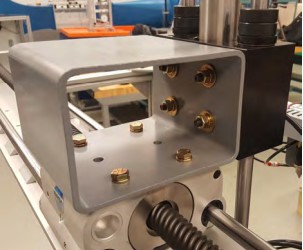
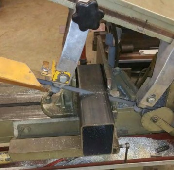
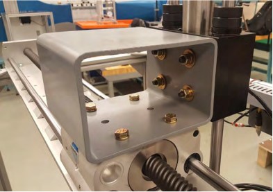
Step 4 – Actuator Connection
The Z direction actuator is now attached to the system by the mount. The mount is a square tube
of steel which is provided by IPFW machine shop. The stock needs to be cut down to be used.
This is measured to the same length as the largest actuator base. This connects the Z actuator
and the X actuator. Eight holes are drilled, four on one side and four on an adjacent side. Bolts,
nuts, washers, and lock washers are utilized to achieve a firm connection to the mount as shown
in Figure 21 below. With a touch of paint, the mount is completed as shown in Figure 22.
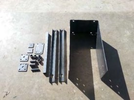
Step 5 – Wrist Fabrication
Using the drawings in Appendix D, the individual components were cut to size and the holes were
drilled. The inner hoop was hand-bent over a half-inch rod to create quarter-inch inner radii. To
facilitate bending by hand, an acetylene torch was used to heat the metal. The individual
components can be seen in Figure 23:
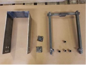
From these components, three weld assemblies were created using a shielded metal arc welder.
Beads were broken up into segments ranging from quarter-inch to half-inch to prevent the metal
from getting too hot. By keeping the metal cool, the amount of warp and chance of blow-though
is reduced. The components before paint can be seen in Figure 24. An additional component was
created to assist the carriage weldment. A 0.625 inch rod with a length of 12.25 inches was
inserted into the bushing housing sub-weldments while assembling the carriage weldment. This
rod keep the two bushing housings in line with each other and helped keep the arms square.
Once the weldment was completed, the rod was cut in two places and removed. The final tasks
were painting the components and bolting the assembly.
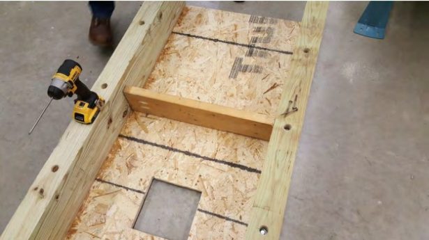
Step 6 – Floor Board
A combination of overlay and OSB board and wood 4”x4”x4’ the bottom of the base is complete.
The thin overlay going on top of the OSB board, these boards are cut to the same profile as the
footprint of the system. The 4×4 goes along the long sides of board. They are screwed in by lag
bolts. The 4x4s will give the platform the required height needed to allow the spacers pin to clear
the ground. A single bar of wood will go across the center of these 4x4s to help retain the distance
and keep the boards from warping upon unexpected forces while moving the system. A square
hole is cut out of the boards as seen in Figure 25 below. This is to allow the space holder to be
placed and positioned.
The spacer stand is created from the same stock metal square tubing used previously in Step 4 –
Actuator Connection. This a great replication of the current GM truck frame. In order to properly
fit the spacers and positioning tolerances, a few materials are added. Peg board, with 1” spacing
is used to create an X and Y variation in the spacer. This apparatus is CNC from the IPFW Haas
Lab. Figure 26, shown below, is the CAD drawing of the design.
After the part is verified through the lab technician, it is then CNC through the mill though G
codes generated by Solidworks add-on programs. Shown below in Figure 27 is the CNC process
of creating the spacer holder. The image in not very clear due to the coolant spray. In Figure 28
shows the finalized product.
The spacer holder is now placed in the void of the board. Connecting the two objects is the peg
board. It is fastened by wall screws. This is done for the powerful grip it provides when the spacer
is in position. Then the testing of this specific location is finished, it can easily be unscrewed,
removed and replaced with minimal efforts and fairly quick. This setup provides up to 10 different
locations for the spacer to exist as shown in Figure 28. This includes changes in both the X and Y
direction.
Step 8 – Pneumatic Panel and Plumbing
The pneumatic panel was created from surplus material for the wrist. The 10GA plate was used
to create a panel six inches tall and twenty-four inches long. Using 10GA plate was excessive in
terms of strength, but the thickness does provide a very rigid mount for the components. Holes
were drilled to match the pneumatic components. The panel was painted to match the wrist and
actuator mount. Two carriage bolts were used to attach the panel to the 8020 frame. The
components were bolted to the panel and plumbed together. The tubes running to the
pneumatic actuator and the magnet are together to run to the electric actuator. The IR sensor
on the bottom of magnet and the magnetic sensor have their wires ran with the pneumatic tubes.
The attachment to the wrist is shown in Figure 29 with a loop to allow for rotation. The harness
is ran to allow movement in the horizontal and vertical directions as shown in Figure 30.