
Introduction
In the beginning of the autumn semester, we came across some videos from Youtube introducing the SDR (Software Defined Radio). We found it very interesting because it has a very broad range of frequency detections and leaves all the filtering & processing stuff to the software. Because of that, it can be applied to receive signals from FM radios, HAM communications, and even satellite signals. Thererfore, we wanted to do some experiments with it. In specific, we were trying to develop and test a design for incorporating this SDR dongle into the Raspberry Pi ecosystem and developing a nice yet simple graphical interface for receiving the live weather image from the NOAA satellites.
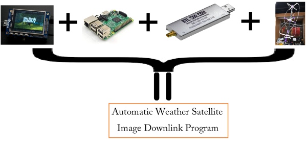
This system is capable of displaying the time remaining for the next satellite overhead event and recording the signals autonomously for decoding. The final outcome of this program is to process/decode the weather images and display them on the touchscreen as they become ready. The tools we used are Raspberry Pi, piTFT touchscreen, SDR USB dongle and satellite signal receiving (QFH) antenna. The figure below shows the components of our design.
Project Objective:
- Build a Quadrifilar Helix Antenna for Weather Satellite Image Receptions
- Develop Shell and Python scripts for recording, decoding, and displaying the acquired images automatically
- Research possibilities on receiving signals from other weather satellites
QFH Antenna
In the beginning, we did some research and considered three different kinds of antenna for receiving signals from NOAA satellites: V-dipole Antenna, Double Cross Antenna and QFH (Quadrifiliar Helix) Antenna.
• V-dipole antenna is the most trivial antenna during the construction. It is based on a very simple linearly polarized dipole. To receive signals from NOAA, we need to set two dipoles with leg length 53.4cm and spread apart 120 degrees. We also have to move the antenna direction based on the location of satellites.
• Double cross antenna contains four dipoles. Each dipole should have length of 38.25 inches and 21.5 inches spacing. Each of the four dipole supports is tilted 30 degrees from vertical. This antenna style has a safety concern: every dipole is sharp-pointed to outside.
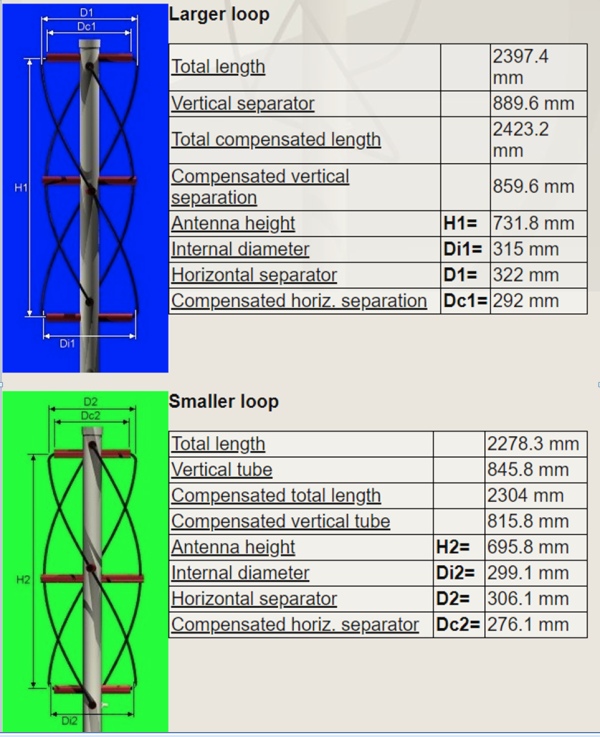
• Unlike previous two styles, Quadrifilar Helix (QFH) antenna contains a single wire that wound in the form of a helix. This antenna is omni-directional and we don’t need to move it based on the location of satellites. Based on the calculation, we need to design the antenna with the following dimension (Picture below on the left)
We finally settled down with building the QFH Antenna because of the its easy-to-build characteristics and that beautiful helix shape. On Nov. 18, 2019, I sent the custom-made STL files to the Rapid Prototype Lab for 3D printing. This included the parts for the top, middle, and bottom mounting brackets. The next day, we picked up those printed parts and headed to the Home Depot for buying suitable pipes and coax cable. On Thursday, we did some initial build by cutting the PVC pipes and then went to Home Depot again for purchasing additional PVC pipe. On Nov. 23, 2019, we met at the ECE Maker Club 3pm in the afternoon and worked on building the antenna. We worked six and a half hours non-stop. In the process, we cut the additional PVC pipe, sticked the 3D printed parts to PVC pipes, measured dimensions, soldered wires, and put it all together. Later that evening, we did an initial test since there's a satellite pass-by at 10:30pm. The antenna worked properly. The picture above on the right is our QFH antenna.
Software Program
In this section, I will discuss the software we implemented for this project. First of all, the driver for the RTL dongle has been installed to raspberry pi. We also installed the sox audio toolkit for post processing the audio stream from satellite. To know when the satellites pass overhead, we installed predict software. In addition, we installed the wxtoimg for audio decoding and weather map generation. After all the software installation process, we implemented scripts to schedule the satellite signal receiving. The first script we implemented is schedule_all.sh, it update satellite information from celestrak and creates a TLE file for prediction use. We also implemented schedule_satellite.sh to calculate each pass event and store the information into atqlog.sat and goodluck.sat, two files that contains the information of each pass event. Then, we impelemented the receive_and_process_satellite.sh, which received the signal from satellites and process it into a wav file. This is the low level software of our Raspberry Pi. As for the interface, we developed the autosat.py with pygame to show the satellites pass events and images received. We also used autosat.py to call receive_and_process_satellite.sh when satellite passing our head. We used autorun.sh to schedule the satellite and start the interface.
Testing
Unlike traditional projects, our project can only be tested outside when the satellites passing overhead. When the satellites passing overhead, we connected our QFH antenna to Raspberry Pi and Raspberry Pi will start recording when the elevation of the satellites and us is greater than 20 degrees. However, during the test, the recording process cannot start automatically though we scheduled the recording using ‘at' commands. There are two possible factors might cause this problem. The first is the connection between RTL dongle and Rpi is not reliable. The second factor is that our python file uses most of the CPU so the power is not enough to start recording. So, we removed the ‘at' command and used subprocess.Popen to run the recording commands.
Results, Conclusion & Future Work
Our system worked as planned after the modification from ‘at' command to python subprocess. Our system achieved to predict the satellite pass time, record the signal and decode the signal to weather image, and all of the above processes is shown on the PiTFT screen. Here is the sample image we received on 12/04/2019 with our system.

In the future work, receiving and decoding Russian Meteor M2 satellite can be added to the system. Meteor M2 has a different way to decode and the image should be clearer than NOAA satellites. Also, this system can also add a feature to listen FM radios. We have successfully received FM radios such as FM 91.7MHz during the testing stage. The signal is strong and clear. In addition, we can also implement a interface to show the sound wave during recording.