
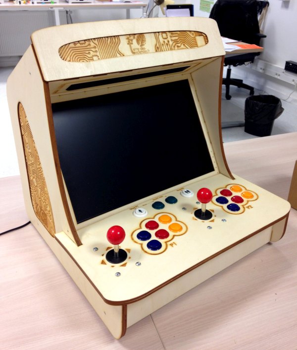
This tutorial offers you to make a Bartop arcade 2 players totally made in laser cutting.
Along with this tutorial, you can also find a Stick Arcade model of this creation (without screen or speakers). The cheaper arcade stick is suitable for more mobile use or for using your computer controls.
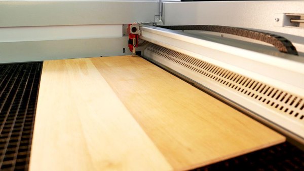
To make this tutorial, you will first need to find out where you can make the 6 laser cuts required to make your terminal. To do this, remember to contact the fablab closest to you!
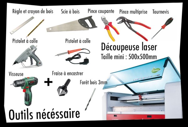
The other tools required for manufacturing are listed in the photos opposite.
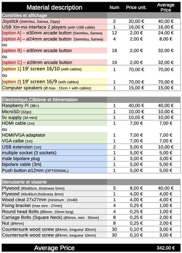
You will also find a complete list of material on the elements necessary for your project. The prices of the various components have been voluntarily rounded up. So see the advertised price as a maximum.
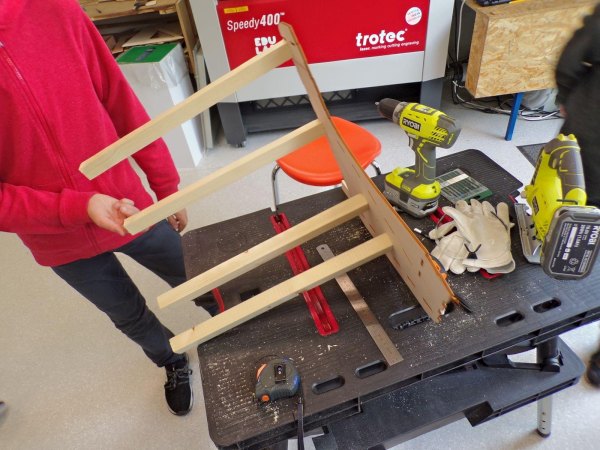
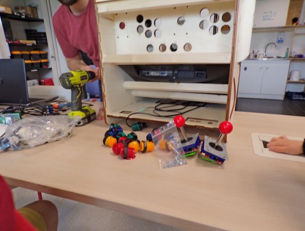
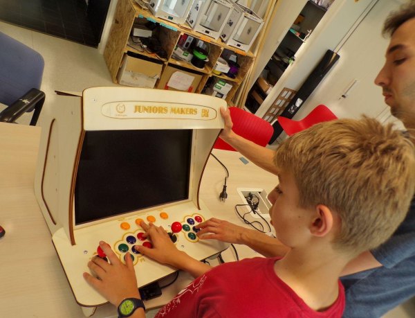
Finally, to support your production, we will be accompanied throughout the tutorial by the photographs of the children of the Maison de Quartier la Bellangerais (Rennes – France), who successfully worked on the manufacture of this object in May / June 2019, accompanied by their host Jérémie Leroy.
If you want to take over this project for yourself, please respect the license (CC-BY-NC), citing the author of the plans: Tony Vanpoucke.
Step 1: Prerequisite Tools
To do this lasercut bartop you will need to use a lasercut machine, so, go to your fablab !!
list of prerequisite tools:
Laser cutting (cutting board size 500x500mm)
Screwdriver / Drill (+ with recessed cutter + 3mm wood drill)
Screwdriver (Phillips and flat)
Pliers
Cutting pliers
Wood saw / jigsaw
Ruler and wooden pencil
Soldering iron (with tin)
Glue gun (with glue refill)
Step 2: Material in Detail
Before ordering the production, you will need some material !
You will find opposite the entire list of items to be purchased divided into 5 categories : Buttons, Display / audio, Electronics, Wiring and Carpentry.
You will surely have noticed some items to choose from in this list. These are the buttons and the screen.
Side buttons you will have the choice between
[Option A] : American style buttons: 16 buttons 28mm in diameter
[Option B] : Japanese style buttons: 16 buttons 30mm in diameter
[Option C] : Japanese style buttons: 12 buttons of 30mm in diameter + 4 secondary buttons of 24mm in diameter
You will therefore have to choose one of these cases from your supplier.
On the screen side, you will have the choice between
[Option 1] : 19 inch screen, 16/10 aspect ratio (recommended)
[Option 2] : 19-inch screen, 16: 9 format
Also be careful about the connections present on your screen, if the latter does not have HDMI you will have to buy a VGA / HDMI adapter to connect it to your Raspberry Pi (computer).
You can therefore order all of the equipment described on the pictures below. Prices shown are rounded up, so consider the total price of the items as a maximum.
Step 3: Prepare Files for Laser Cutting
Now that you've ordered and while you're waiting to collect all of your gear, get ready to sort (and maybe edit) the plans that match your gear.
So let's start by sorting the downloadable plans, choose:
– Pad option A for a set of Ø24 and Ø30mm buttons
[or]
– Pad option B for a complete set of Ø30mm buttons
[or]
– Pad option C for a complete set of Ø 28mm buttons
[and]
– Screen option 1 for a 16/10 screen (recommended)
[or]
– Screen option 2 for a 16: 9 screen
Secondly, check that your joystick model is compatible with your set of plans:
To do this, find the model plans of your joystick with a search engine (the plans look like the diagram opposite). If you don't know it, you can directly measure the distance of the holes in your joystick with a ruler once you have it.
The joystick layout of the original plans is based on the most common joysticks available on the internet (as in the diagram: 4 holes arranged in a rectangle of approximately 80x40mm), you will probably not need to modify your plans. However, if these differ too much, you will have to modify the plans, to do this using the vector software of your choice. You can ask your fablab or on the internet for advice. Be careful then to modify the two layers of the button panel to avoid unpleasant surprises during assembly.
Finally, once the material has been collected and the plans modified, you can cut with a laser, fab lab, or by your own means, the set of plans necessary for the manufacture of your Stick.
Step 4: Countersink the Holes
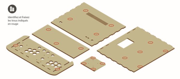
Once your wooden parts are out of laser cutting, get a screwdriver equipped with a built-in cutter. With the screwdriver, slightly bevel all the points marked in red on the plan.
Step 5: Assemble the Back
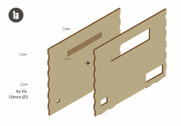
Once the pieces have been countersunk, you can start by assembling the two back pieces together with 10mm screws. Be careful, however, to align the two parts of the back by the flat top edge (see photo).
Step 6: Assemble the Top
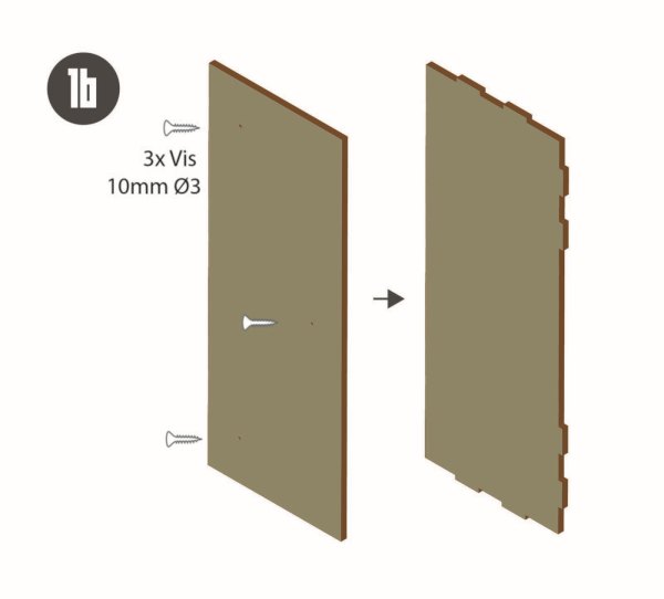
Then assemble the two top pieces of the bartop with 10mm screws. Once again, you will have to align the two pieces well on the flat edge (see photo).
Step 7: Assemble the Speaker Block
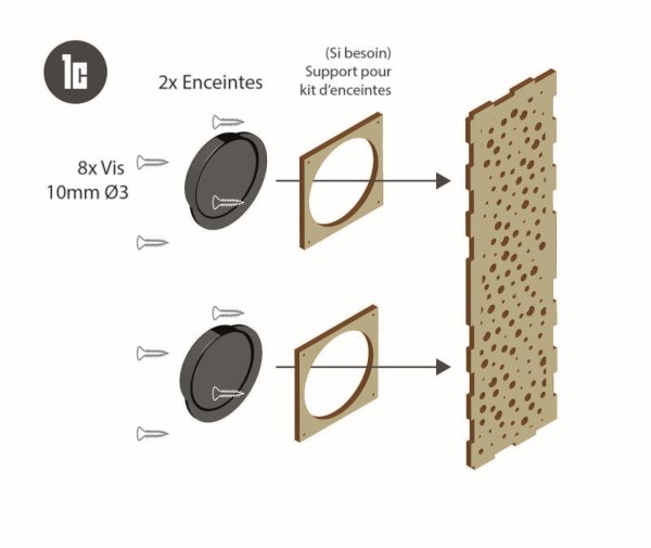
Finally, we will assemble the “enclosure block”. In our example, we took speakers from recovered computers. If this is your case, you will have to take them out of their case and recover the bare parts (from the moment they are bare, it is very dangerous to connect these speakers, so do so only to test, out of the box. reach of any children). All you need to do is aim at the speakers as well as the components on the back of the wooden speaker grille (see photo).
If you have chosen Ø 10cm speaker kit, you can use the wooden speaker stands (in the diagram) to install them against the grille. All you have to do is connect your two speakers to your preamp.
Step 8: Start the Structure!
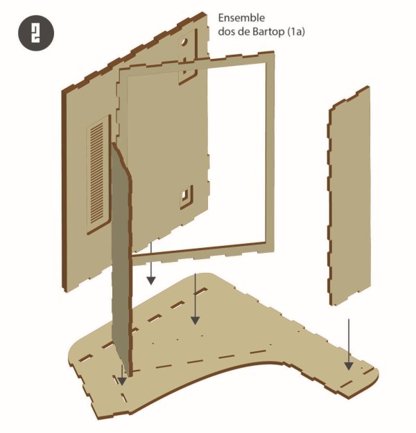
It is from now on that we attack the mounting of the terminal:
To start, place one side on a table and insert the following parts according to the diagram: Back unit, speaker unit, front of the terminal, screen support …
Step 9: Assemble a Side and Face Elements
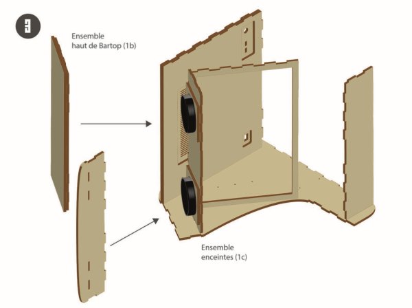
… plus add the block above, and the “marquee” (capital in French), one fitting into the other (see photo). At that time the terminal is not yet standing,
Step 10: Prepare the Assembly on Both Sides With the Cleats
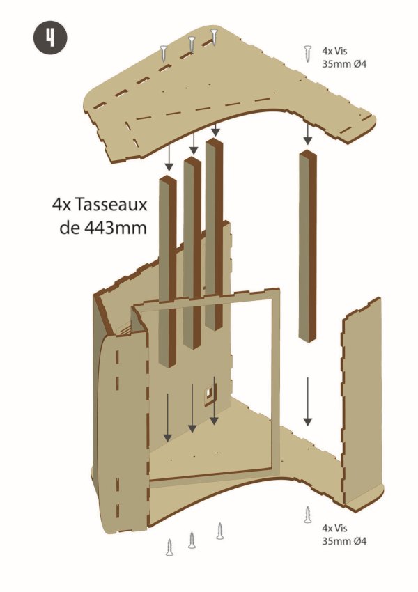
Cut a total of 6 x 44.3 cm cleats. On each end of each cleat, mark the center of each side. Take your screwdriver equipped with a Ø 3mm wood bit and pre-drill all the cleats at the marked locations.
Finally, grab the second side of the bartop and start fixing the first four cleats (see photo).
Step 11: Join the Two Sides to Give Body to the Bartop!
With this side reinforced with cleats, come and insert it into the assembly remained on the table. Make sure that all the slots fit well on top and on the bottom of the bollard.
Once everything is well nested, turn the bollard over (be careful not to drop it, otherwise you will have to redo the step), then aim at the cleats on the freshly turned upside so that the skeleton of the bollard is finished and solid!
Step 12: Prepare Yout Screen
An important step, oh so important, we are now going to place the screen in the Bartop. We can do this in different ways.
But first of all: Try to fit the screen with its box into the bartop (see step 11).
If it fits, it's perfect, you won't need the wooden block-screen rulers. Otherwise, you will have to remove the screen shell to recover the bare slab.
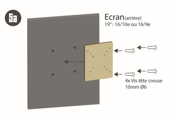
Then, you can fix the socket head screws in the screen wedge rules, we advise you to put two of them, but if you do not have the place one will be enough (see a photo of the step). Be careful, if the socket head screws do not go through the rule completely, you can countersink their hole harder.
Step 13: Assemble the Screen
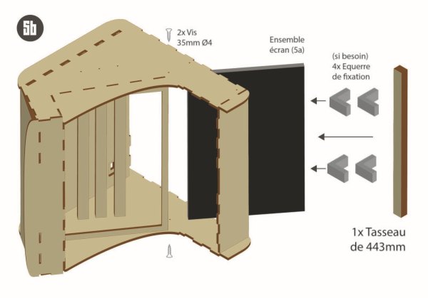
Once again, if your screen fits with its case, simply slide it into the Bartop as in the photos. Otherwise, you will have to pass the screen bare with its wooden ruler fixed in the Bartop. Then you will have to center the screen well from the inside so that no edge can protrude on the outside face on the player side. Once centered, attach 4 brackets to the central cleats and to the screen ruler.
Step 14: Complete the Box
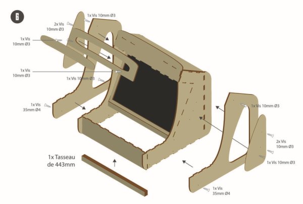
With your screen now in place, you can assemble the few Bartop consolidation pieces (see diagram). Start by adding a fifth cleat in front of the bollard, then aim at it on each side. Then screw the Marquee on the front and sides and fix their personalized decoration, engraved in the wood 3mm.
Step 15: Install the Button Panel
Now, it will be time to tackle the heart of the manufacture of your Bartop: the assembly of the controls.
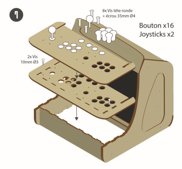
First, you will need to install the button panel. To do this, install the first layer of the panel (with the slots) and insert it in its location (see photo). Then aim this first part at the rest of the Bartop. Once done, put the second layer on top of the first as in the photos.
Step 16: Attach the First P2 Joystick
To fix the wood panel, we are going to install the joysticks. To do this, take the joysticks, and remove the targeted “ball top” as well as the plastic covers.
Inside the Bartop (placed on its back), insert the first joystick facing the 4 corresponding holes on the “P2” side, then quickly pass the 4 bolts on the panel side to finish aiming the bolts through and secure your joystick.
Step 17: Attach the Second Joystick P1 (with Optional Manipulation)
Joystick P1 is inserted in the same way as joystick P2. But there may be a little subtlety. If you have with you a joystick with 5 pins coming out from one side of the joystick *, you just have to insert your joystick so as to point the pins towards this center of the terminal.
If you have (as in the photos) a Zippy-type joystick, with 2 pins coming out of each side of the joystick, you will have to do a little manipulation. Take your joystick and gently twist the pins on one of the sides so that you can secure it in the left corner of the Bartop without being in the way.
Step 18: Tighten the Joysticks
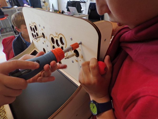
Once the two joysticks are in place, it's time to tighten. With a wrench suitable for the diameter of the bolt or water pump pliers, hold the bolts one by one while someone else is tightening on the other side. Note that if you have the recommended bolts (button head bolt) you will need to aim at the bolt and a third person will not be needed.
Also, even if the tightening can be laborious, we advise you to tighten the bolts well at the risk of seeing your joysticks “swim” in the void as you go.
Finally end by screwing, put the black plastic washer on the axis of the joystick, and screw the “balltop” at the top of the latter. To help yourself you can, with a flat screwdriver, hold the joystick bar for a firmer face.
Step 19: Install the Buttons
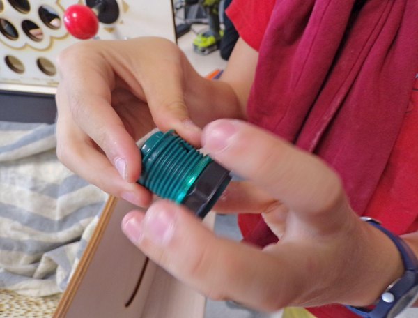
Now that the hard part is over, we will breathe a little while installing the buttons. To do this, take the buttons and remove the sighted or floating parts. Pass the buttons through the holes in the wood panel in the order of your choice. Then attach the buttons from inside the Bartop.
Step 20: Connect the GND of the Boutons
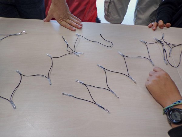
Then, take the two cables often taking the form of garlands (see photo), and connect all the “buttons and directions” joystick (called “microswitches”) of P1, and with the second cable all the buttons and of the P2 directions. There must then be a pin remaining on each button and each microswitch of the joysticks, we very quickly connect them …
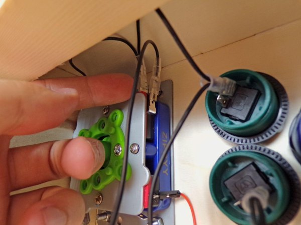
Step 21: Connect the GND of the Second Joystick (optional Manipulation)
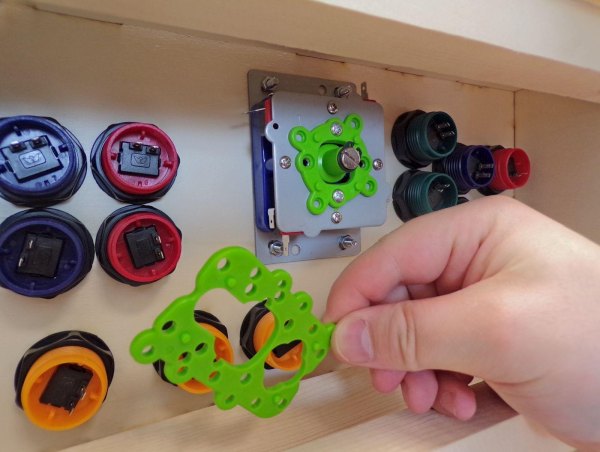
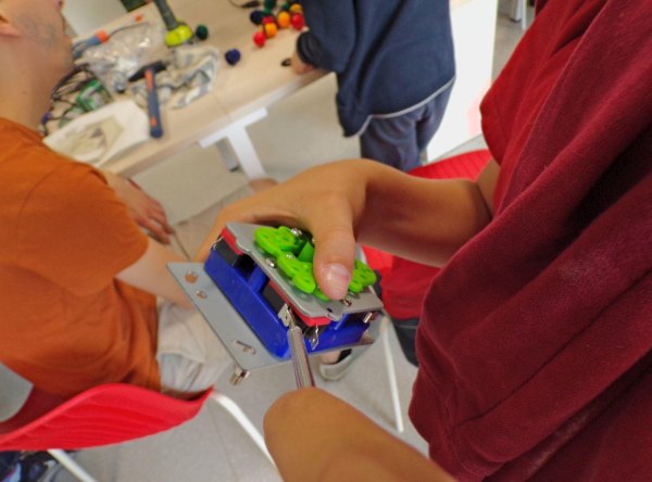
But you may have difficulty connecting the cables to the “P1” joystick.
If this is your case, we advise you to remove the joystick by unscrewing its metal plate (the latter is now the “micro-switches”) (see photo). Once disassembled you can more easily connect the pins of the joystick. When you're done, all you have to do is close the joystick with its microswitches plugged in.
Step 22: Connect the Remaining Pins of the Buttons and Joysticks
Read the connection diagram for the next step (step 22). You can now connect with the cables (often arranged in bundles of 2 or 4 pins) to all the buttons and microswitches of the joysticks.
Step 23: Connect All Pins to Your Interface
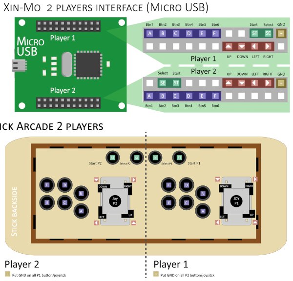
Before plugging the head into the handlebars of your Bartop, check the model of your interface. We offer here the connection models for the Xin-mo interfaces (the “zero-delay” interfaces, which are also very widespread, and do not need plans).
There are two models of Xin-mo 2players: one with a micro USB (and a total of 44pins) and one with a standard USB (and a total of 36pins). So choose the plan corresponding to the model of your interface and connect all the controls.
Step 24: Attach Additional USBs to Your Bartop
Now that your controls are connected (we will check them later) let's move on to the connections of your Bartop.
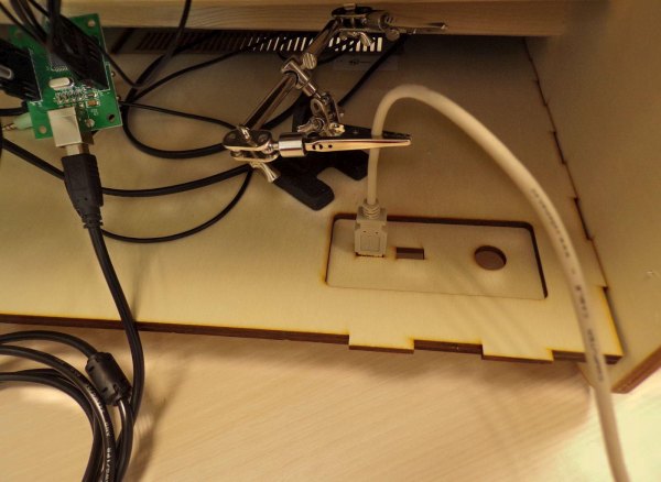
To do this, start by taking your two USB extension cables and using a “third hand” clamp (or your own hand) to hold the cable while you attach the female side of your extension cable to the back of the cable. terminal. To fix everything we use a glue gun, but you are free to use something else.
Step 25: Install the Power Supply for Your Bartop
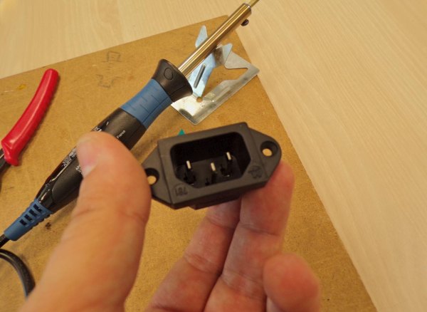
Now that the secondary USBs have been attached, take your power strip and the bipolar base (in the photos we have used a three-pole base).
Cut your power strip as in the photo and take out the 3 wires from the power cable that you will strip. In these 3 threads alone, the red and blue threads interest us. Then connect the blue and red wires in either direction on the reverse side of your bipolar socket without the third wire (green and yellow) (the latter is not mandatory for your use, but if you have a 3-pole socket like in the photos, you can put it on the base without problems).
Once the two (or three) wires are placed on the two (or three) terminals of the base, solder them with a soldering iron. Finally, to protect everything and that no one puts their fingers directly on the socket: it is ESSENTIAL to insulate the wires welded to the base. To do this we poured them into the plastic with the glue gun.
Step 26: Plugin Your Raspberry Pi
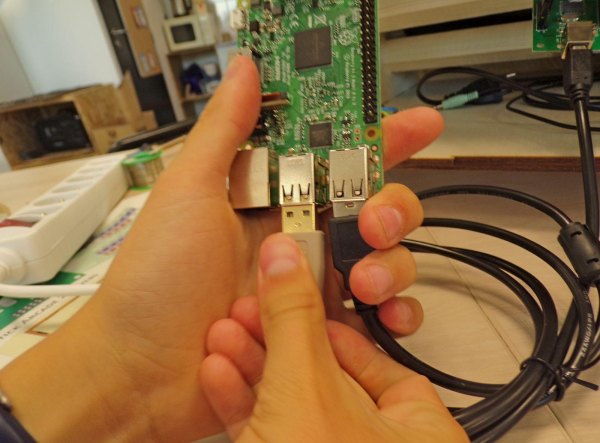
We are there, now that all the connections are ready, all you have to do is connect the whole thing to your Raspberry pi. To do all this: first, connect the two USB extension cords to the Rasberry's USB ports, then connect the speaker plug to the power strip and the jack of these behind to the jack port of the card. Then connect the HDMI of the screen to the microcomputer.
If your display is equipped with a VGA port, you will need a VGA / HDMI box to connect to the Raspberry pi.
Now take the USB from the button interface for the branch to one of the 2 remaining USBs of the Raspberry pi.
Finally, you can connect the power supply of the card to the multiple sockets.
Step 27: Install the Power Strip
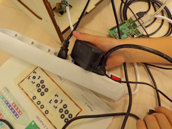
Normally you should have 3 sockets connected to the power strip (speakers, screen, and raspberry pi). Take the power strip and using the glue gun fix it to the bottom of the Bartop.
Step 28: Install an SD Image for Your Raspberry Pi!
That's it you got there, your Bartop is almost finished!
To operate your Rasberry Pi, you will need an operating system dedicated to video game emulation. To do this, go back to your computer equipped with SD support and with your memory card.
There are a few operating systems for emulation stations that you can use freely:
Recalbox (well known in the French-speaking community)
Batocera (a variant of Recalbox, more and more popular)
Retropie (famous and widely used distribution around the world, very active English-speaking community)
Lakka (also very famous software with an interface inspired by the menu of the PSP console)
To find out how to install this operating system, go to this tutorial, the operation is quite easy to set up!
There are other systems that offer various interfaces and functionality, so be curious and test several if you feel like it.
Step 29: Test the Buttons Before Closing the Bartop
Rest the Bartop normally on the table and connect the power cable to the back of the latter. Wait and cross your fingers for everything to start well.
If your Raspberry-pi starts well and you fall into the emulation interface (Recalbox or Retropie). Test the controls to see if they respond well. First, check that the J1 behaves in the same way as the J2. If this is the case, you can refine your tests in a game including all the Bartop buttons (a fighting game, such as Street Fighter is perfect for this kind of test).
After testing, if the controls malfunction, you will need to revise the button/joystick connections.
Step 30:
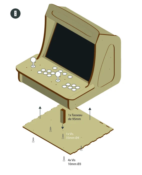
Are the controls working ? Perfect ! you are almost done!
Cut a last 95mm cleat and attach it to the last piece still on the side (the underside of the terminal). Then close the underside of the terminal at Bartop.
Here is your Bartop is ready for long hours of play !!
Source: Bartop 2 Players – Laser Cut