
switching voltage regulator is one of my favorite circuits. In school, they were the first circuits I built where I understood how transistors worked. In fact, they were the first circuit I saw an inductor being useful! Switching regulators are incredibly efficient when designed properly. Of course, this detail about design is important. They are not as simple as a linear regulator, which is basically an IC and two caps.
To understand the basics of a switching regulator, I released AddOhms #18 this week. This is video tutorial dedicated the Switching Voltage Regulator. If video tutorials aren’t your thing, then keep reading for my written tutorial.
Switching Voltage Regulator Introduction
There are two major types of Voltage Regulators: Linear and Switching. For a higher level introduction, check out my earlier Voltage Regulator Tutorial.
Linear Regulator Example
Linear regulators only need a small number of components, are simple to add to a board, but are not very efficient. Switching regulators can be made to be very efficient for a particular circuit, but can be difficult to design.
Back on AddOhms #17, we talked about how Linear Regulators work. In this tutorial, we are looking at switching regulators.
Switch-Mode Converter Core Components
There are 4 core components needed in a switching voltage regulator.
Capacitors
Capacitors store energy in an electric field. When a voltage is applied, the capacitor charges up. When the voltage goes away, the capacitor discharges.
Inductors
Inductors store energy in a magnetic field. When current flows through the inductor, a magnetic field is created. When the current stops, the magnetic field collapses generating current.
Switching voltage regulators work by making use of the energy storage properties of a capacitor and an inductor. To control the charge and discharge of these components, we use diodes and transistors.
Diodes
As we discussed in AddOhms #8, diodes only allow current to flow in one direction. Later, we’ll see what that is important.
Switches (or Transistors)
The switch or transistor used to control the regulator is why we call them “switching regulators.”
Transistor in Switching Voltage Regulator
When the switch is “off” no current flows through it. No current flowing, means no power wasted. When the switch is “on” the voltage drop across the switch is 0 volts. So again, no power is wasted. Typically a MOSFET is used for the transistor, however, it is possible to build a converter with a BJT.
Now that we have all of the components let’s combine them together.
Buck Converter
A buck converter, also called a step-down converter, will create an output voltage lower than its input voltage. This is similar to how linear regulators, like the LM7805, work.
The inductor tries to keep current flowing while the capacitor tries to keep the voltage constant. When we connect the inductor to the capacitor, the inductor becomes a current source, and the capacitor becomes a voltage source.
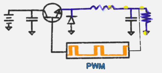
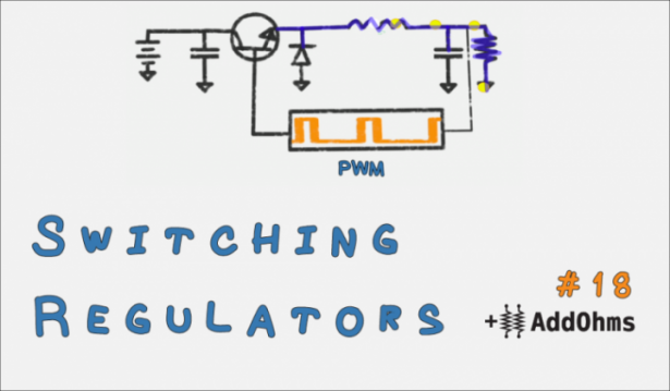
Buck Converter with PWM
The transistor is used to control the charging and discharge of the inductor. For example, you could use Pulse Width Modulation to control how long the inductor is charged and discharged.
In an ideal circuit, all of these components would have no power loss. In reality, these all burn a little bit of power, which is known as switching losses.
For More Details: Basic Switching Voltage Regulator Tutorial