
Many cameras have a 2.5mm audio jack in the side for a remote shutter release cable, and it can be used to wake up the camera if it has gone into power-save move and also take pictures. For now, I have only tested this against the Canon Rebel XSi, but it looks like the same accessory that works for that camera will also work on most of the Canon DSLRs out there. Much of what I figured out was with the help of this Camera Hacker article which gives the pin connections discussed below.
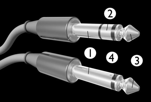 The 2.5mm jack used to connect the camera to a shutter-release device is shown on the right. The top jack shown is the stereo version which is used in the cameras, so make sure that middle ring is present in any cable or jack that you use. The jack is wired as follows: (1) Ground, (2) Focus, (3) Shutter. Connecting the wire from (2) to ground (1) will cause the camera to focus, while connecting (3) to ground will cause the camera to take a picture. Technically, you can think of connecting (3) to ground as the equivalent of holding your finger down on the shutter button… if you have it in multi-frame mode, it will take a sequence of pictures until you disconnect (3) from ground.
Required parts
Below is a list of parts needed to follow the technique discussed on this page.
- Canon EOS camera (other models may work, but check the interwebs for connection details first!)
- 2.5mm Stereo audio cable OR 3-conductor stereo wire and a bare 2.5mm stero jack
- Breadboard
- Raspbery Pi prepped as discussed in Getting Started
- AdaFruit's Pi Cobbler breakout board for Raspberry Pi, OR other means of connecting GPIO pins on the Pi to the breadboard.
- 2N2222 transistors (qty 2)
- 470 ohm resistors (qty 2)
Wiring
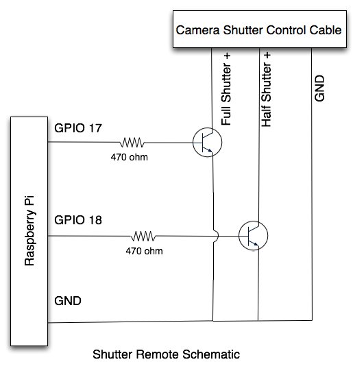
With the above parts, can create a circuit on a breadboard to allow the GPIO pins on the Pi to control the camera's focus and shutter funtions via the remote connection port. A schematic is shown in Figure 2. As shown, the circuit uses the 2N2222 transistor to make the connection between the full shutter (+) line and ground when GPIO 17 is set high. The GPIO pin is connected to the base of the transistor through a 470 ohm resistor. Likewise, a transistor is used to connect the Half Shutter (Focus) to ground when GPIO 18 is set high. Simple!
For more detail: Camera control via shutter release cable