
As I said in the previous part, I’m not an electrical engineer. I haven’t touched any real electronics since school. However, the internet is a wonderful place, and thanks to a number of other sources I was able to figure out how to get the Pi to drive a couple of motors. Essentially this guide will tell you how to wire up a couple of DC motors to the Raspberry Pi, even if you’re not following the whole build to the letter.
Here are my references:
Thanks to the authors for writing down their work.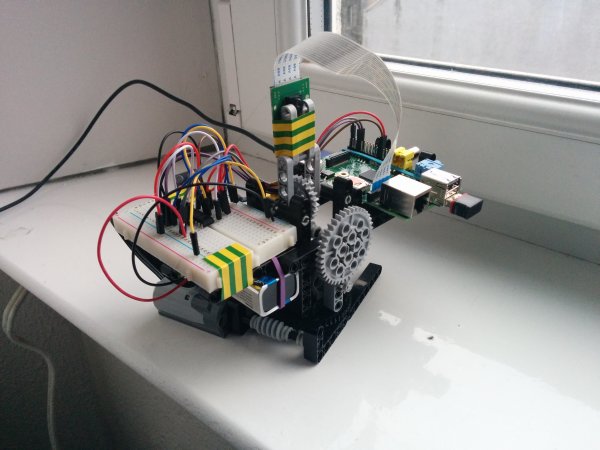 To make life easier, I bought a bunch of these jumper cables for about £3.50, mostly male to male to go between breadboard etc, but also some male to female to go between breadboard and the Pi’s GPIO headers.
A DC motor will spin one way depending on which pole you attach the positive/negative to, and will spin the other way when you swap them around. I picked up a couple of these L293D stepper motor drivers. Each of these integrated circuits let you control 2 DC motors, so one of them is spare
The other electronic parts I picked up are as follows:
- A few 9v PP3 batteries (buy one get one free! Cool!)
- Battery clips for said batteries
- Breadboard
- Electrical tape
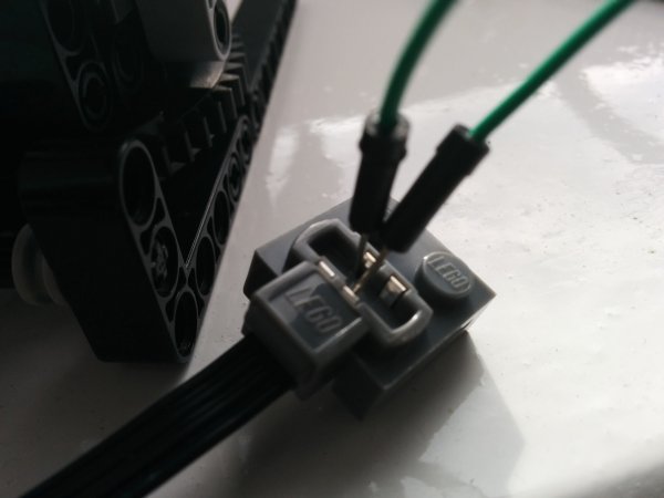
One of the concerns I had was that the 8883 Lego motors have 4 wires (rather than the usual 2 for a motor) and connectors that can be stacked with other Lego bricks. This is all well and good, but not really designed to be connected to breadboard. However, the metal contacts in the connectors are sprung, so you can wedge a wire in them pretty safely:
The 2 inner connectors (which are actually facing each other) are the positive and negative poles of the motor. Here I’ve simply wedged a couple of jumper leads into the contacts. Its actually pretty solid and I’d have to really put a bit of force on them to short them out or move them around. Its very important that you don’t short the motor connection here. The outer wires aren’t connected with these motors but are used by other Lego ‘Power Functions’ parts if you ever happen to stack the connectors together.
There are a couple of ways to refer to the GPIO pins on the Pi. I’ll be referring to the pins as the computer understands them (BCM mode). When you hold the Pi in front of you with the SD card slot on the left, BCM numbering on revision 2 boards looks like this:
You’ll be using any 4 of the green pins: 2 for each motor (+ and – per motor) and a 5th for the 5v pin. Its a good idea to write down what you’re using:
- GPIO04 = Elevation motor +ve
- GPIO14 = Elevation motor -ve
- GPIO09 = Rotation motor +ve
- GPIO25 = Rotation motor -ve
 I actually don’t know which pin is which on the motors, I’m just connecting them up, and I can decide later which direction is which when I write scripts to turn the motors over. This is the breadboard diagram of the whole thing:
Pins 1 and 9 on the L239D are ‘enable’ pins for each of the 2 motors. This would allow you to wire up a sort of ‘master’ switch for each motor, or use pulse width modulation to control motor speed. I don’t really care about that, so here I’ve just wired both pins 1 and 9 to the 5v output of the Pi, which enables both motor channels whenever the Pi is on. The rotation of the motors is handled by switching ‘on’ the other pins.
For more detail: Camera Platform Electronics