
Reverse engineering CAN bus data from an EV.
Introduction
In connected cars manufacturers gather diagnostic data and transmit them for field studies or planed maintenance. The GSM modem in my smart electric drive EV was in this mode for a certain time. I wanted to know what information was gathered and began to analyze the CAN bus traffic of the car.
Digging into the CAN bus protocol I managed to reverse engineer queries for the cell voltages and the cell capacities. Beside the diagnostic information there is a lot of useful data about the status of the car…
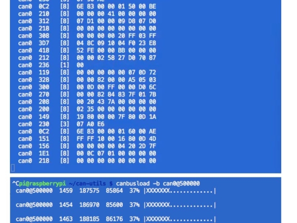
When sniffing and logging the complete CAN bus traffic, you need a fast processor. An Arduino based logger, saving the sniffed data to a SD-card, is often not fast enough for capturing the whole traffic. Most cars use a 500kbit/s data rate (or above) and with a bus load of 40% you will have to save about 1500 messages per second.
For this purpose a Raspberry Pi is a very capable platform. Get a CAN bus shield like the PICAN and install the free CAN utils software. This is a socket CAN driver and utility package.
You will find a very useful tutorial about everything you need to know about CAN bus on a RPi from the CowFish team here . Also take a look at the site of Chad Gibbons. So get the hardware and prepare the RPi for the CAN utils and start sniffing…
But for what are we looking? The high voltage battery of the Smart ED consist of 93 lithium ion cells. A battery management system is controlling them and will store the data. When the GSM modem requests the cell voltages, there will be a “large” set of data, send in blocks. 93 cells with high- and low-byte are at least 186 bytes + some more control-messages.
CAN message data structure
So lets look at the data structure on CAN bus messages:
can0 00F [8] 53 6D 61 72 74 2D 45 44
can0is the name of the interface on the RPi00Fis a CAN message ID[8]will give you the data length in bytes- then those payload bytes will follow:
53 6D 61 72 74 2D 45 44
The messages are transmitted on a shared bus system and data collision must be avoided:
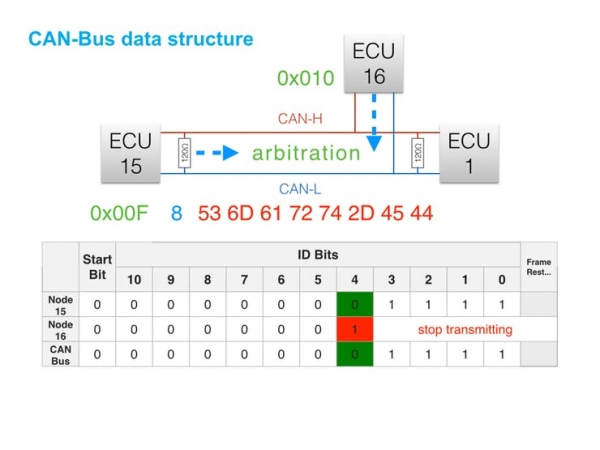
ECU 15 (ID 0x00F) wants to transmit data to ECU 1. If ECU 16 (ID 0x010) is going to send data in the same moment, those two messages will collide. The arbitration mechanism will prevent this collision, because ECU 16 will probe each Bit of it's ID (starting with the MSB) and will stop, if an other ID is already sending. So lower IDs will have a higher priority and can interrupt higher IDs from being sent.
When searching for diagnostic information, you will have to look at high IDs mostly in the range of 0x700 and above.
When scanning set filters to show only the selected ID range and skip all other IDs.
A First Success
While searching for those IDs I stumbled across this interesting packet:
can0  7E7   [8]  03 22 02 08 FF FF FF FF
  can0  7EF   [8]  11 93 62 02 08 0E A7 0E
  can0  7E7   [8]  30 08 14 FF FF FF FF FF
  can0  7EF   [8]  21 A9 0E A5 0E AD 0E AC
  can0  7EF   [8]  22 0E A6 0E AB 0E A4 0E
  can0  7EF   [8]  23 AD 0E A6 0E A9 0E AB
  can0  7EF   [8]  24 0E AC 0E A4 0E A9 0E
  can0  7EF   [8]  25 A4 0E AE 0E AA 0E AD
  can0  7EF   [8]  26 0E AB 0E AA 0E A9 0E
  can0  7EF   [8]  27 A3 0E AA 0E A6 0E A8
  can0  7EF   [8]  28 0E AC 0E AB 0E AE 0E
  can0  7E7   [8]  30 08 14 FF FF FF FF FF
  can0  7EF   [8]  29 92 0E A7 0E A5 0E AD
  can0  7EF   [8]  2A 0E AA 0E AA 0E A7 0E
  can0  7EF   [8]  2B A4 0E 9F 0E A2 0E AC
  can0  7EF   [8]  2C 0E AB 0E AD 0E A5 0E
  can0  7EF   [8]  2D A4 0E A5 0E A8 0E AD
  can0  7EF   [8]  2E 0E A8 0E A1 0E A6 0E
  can0  7EF   [8]  2F A5 0E A7 0E A8 0E A4
  can0  7EF   [8]  20 0E AA 0E AD 0E A7 0E
  can0  7E7   [8]  30 08 14 FF FF FF FF FF
  can0  7EF   [8]  21 A4 0E AB 0E A3 0E A2
  can0  7EF   [8]  22 0E A6 0E AA 0E A8 0E
  can0  7EF   [8]  23 AD 0E AF 0E AE 0E AE
  can0  7EF   [8]  24 0E AB 0E AD 0E AB 0E
  can0  7EF   [8]  25 A9 0E A6 0E A4 0E A5
  can0  7EF   [8]  26 0E AA 0E A1 0E A2 0E
  can0  7EF   [8]  27 A0 0E 9B 0E A2 0E A0
  can0  7EF   [8]  28 0E 90 0E 9F 0E A1 0E
  can0  7E7   [8]  30 08 14 FF FF FF FF FF
  can0  7EF   [8]  29 9E 0E 9C 0E A2 0E A1
  can0  7EF   [8]  2A 0E 9F 0E A4 0E 9D 0E
  can0  7EF   [8]  2B A1 FF FF FF FF FF FF
  can0  7EF   [8]  2C FF FF FF FF FF FF FF
  can0  7EF   [8]  2D FF FF FF FF FF FF FF
  can0  7EF   [8]  2E FF FF FF FF FF FF FF
The active IDs are 0x7E7 and 0x7EF. The request is sent to ID 0x7E7 and the listening ECU is responding with an offset of 0x008 using a message ID of 0x7EF.
Transport Layer
This behaviour and the data structure is described by transport protocols like ISO 15765-2 and the Unified Diagnostic Service.
You will find useful information about the CAN bus and the transport layer here:
Decoding Cell Voltages and Cell Capacities
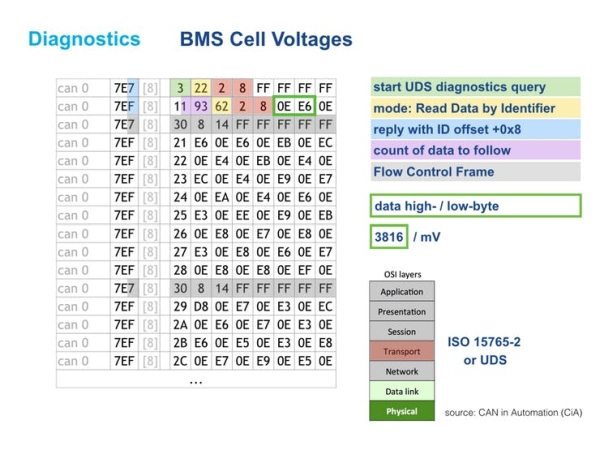
With this knowledge you can identify two-byte-data consisting of high- and low-byte carrying plausible content.
The BMS software in the Smart ED seems to handle 200 cells in total, so there will be data for 93 cells and the rest on the multi frame message is filled with 0xFF values.
The cell voltage request will give you 0x193 bytes of data – equal to 403 bytes. Three bytes are for the UDS response 62 02 08 and then 400 = 200 high-/ low-bytes follow…
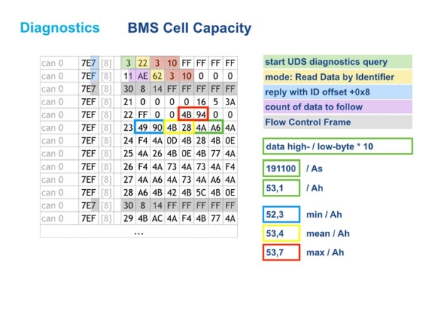
Within the capacity request additional data is buried, so there will be 430 bytes in this answer (equal to 0x1AE):
Using these queries I have built my own diagnostics tool using an Arduino Uno & a CAN bus shield. You find the project tutorial here.
I hope you are now inspired for finding useful information within your car's CAN bus.
Have fun!
Source: CAN Bus Sniffing