
Raspberry Pi is an ARM architecture processor based board designed for electronic engineers and hobbyists. The PI is one of most trusted project development platforms out there now. With higher processor speed and 1 GB RAM, the PI can be used for many high profile projects like Image processing and Internet of Things.
For doing any of high profile projects, one need to understand the basic functions of PI. We will be covering all the basic functionalities of Raspberry Pi in these tutorials. In each tutorial we will discuss one of functions of PI. By the end of this Raspberry Pi Tutorial Series, you will be able to do high profile projects by yourself. Go through below tutorials:
- Getting Started with Raspberry Pi
- Raspberry Pi Configuration
- LED Blinky
- Raspberry Pi Button Interfacing
- Raspberry Pi PWM generation
- Controlling DC Motor using Raspberry Pi
- Stepper Motor Control with Raspberry Pi
- Interfacing Shift Register with Raspberry Pi
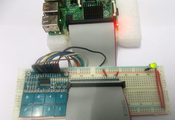
In this tutorial, we will Interface a Capacitive Touchpad to Raspberry Pi. Capacitive Touchpad has 8 keys from 1 to 8. These keys are not exactly keys, they are Touch Sensitive Pads placed on the PCB. When we touch one of the pads, the pads experience the change of capacitance on its surface. This change is captured by the control unit and control unit, as a response, pulls a corresponding pin high at the output side.
We will attach this Capacitive Touchpad Sensor Module to the Raspberry Pi, to use it as input device for the PI.
We will discuss a bit about Raspberry Pi GPIO Pins before going any further.
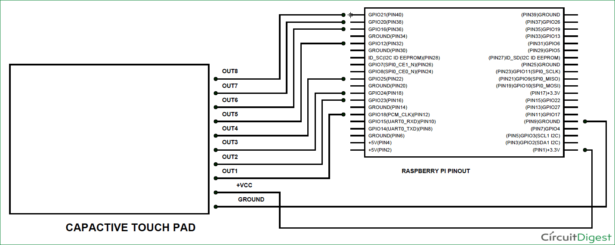
As shown in above figure, there are 40output pins for the PI. But when you look at the second figure below, you can see not all 40 pin out can be programmed to our use. These are only 26 GPIO pins which can be programmed. These pins go from GPIO2 to GPIO27.
These 26 GPIO pins can be programmed as per need. Some of these pins also perform some special functions, we will discuss about that later. With special GPIO put aside, we have 17 GPIO remaining (Light green Color).
Each of these 17 GPIO pins can deliver a maximum of 15mA current. And the sum of currents from all GPIO cannot exceed 50mA. So we can draw a maximum of 3mA in average from each of these GPIO pins. So one should not tamper with these things unless you know what you are doing.
Now another important thing here is that, PI logic control is of +3.3v, so you cannot give more than +3.3V logic to GPIO pin of PI. If you give +5V to any GPIO pin of PI, the board gets damaged. So we need to power the Capacitive Touchpad by +3.3V, for getting proper logic outputs for PI.
Components Required:
Here we are using Raspberry Pi 2 Model B with Raspbian Jessie OS. All the basic Hardware and Software requirements are previously discussed, you can look it up in the Raspberry Pi Introduction, other than that we need:
- Connecting pins
- Capacitive Touch Pad
Circuit Diagram:
For more detail: Capacitive Touch Pad with Raspberry Pi