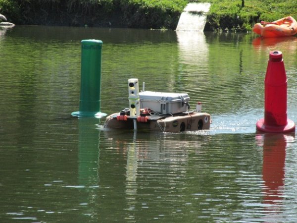
In Part 1, Sergio described the RoboBoat Competition and introduced our entry, the Cedarville University RoboBoat team. In this article, we will go into depth with regards to how we programmed our autonomous aquatic vehicle’s PC and five Raspberry Pi’s using MATLAB and Simulink.
Last year we implemented high level control, image processing and computer vision on the PC. In order to increase the frame rate of our image processing we investigated a couple of different options.
Our first thought was to use multiprocessing since it allows many systems to be running simultaneously and takes full advantage of today’s multicore processors. We found that although MATLAB has timer objects that allow users to implement multithreading on a single core, multiple cores on a CPU could not be utilized, as MATLAB does not support multi-processing beyond parallel loop structures.

Main Code
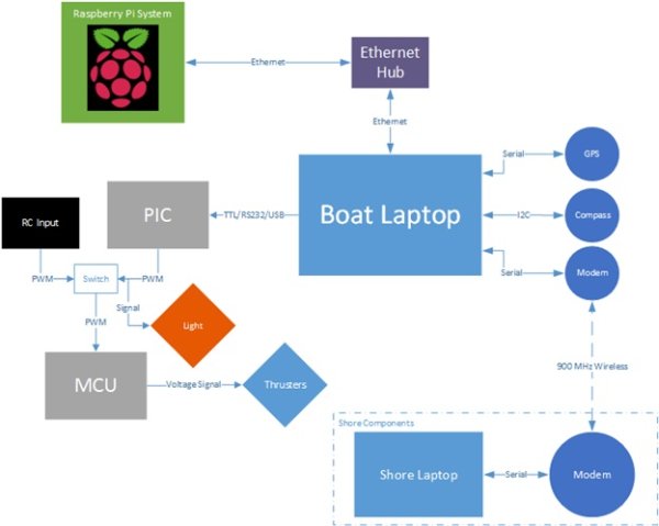
We wrote the main MATLAB GUI program on the Boat Laptop and structured the code to support parallelized operations and event-driven communication to devices. Part of this parallelization was achieved by offloading the image and acoustic processing algorithms to a Raspberry Pi network. This increased the code’s modularity, performance and ease of debugging.
After doing some research on how MATLAB connects to devices, we found out that communication and timer objects supports asynchronous events. These event based functions are usually called callbacks. Device communications events (like a UDP or Serial buffer reaching a certain number of bytes or getting a terminator character) could also be assigned callback functions. Along with that, we found that MATLAB had asynchronous send functions where data would be written to the output buffer and forgotten about. We also found that MATLAB could use timers to trigger events, and decided that a fixed-period timer event would be ideal for executing our PID algorithms.
Networking
Since many of the systems take a long time to complete we needed a way to improve performance. As a cheap alternative to replacing our system with expensive hardware we created a way to offload the majority of the computations that our main laptop was performing onto a network of Raspberry Pis, increasing the stability and consistency of the boat’s actions. By taking the majority of the computations off of the boat laptop, it could now focus on high-level decision-making based on information fed to it from the Raspberry Pis.
The Raspberry Pi network currently consists of five Raspberry Pis and a central laptop all connected using UDP. We installed an Ethernet switch in order to link all the communication lines together. Each Pi sends back pertinent data over a specific UDP port for the boat laptop to decipher and adjust the thrusters and camera servo. The benefit of having a system like this enables the Pis to work independently while the boat laptop continues to work through each event. As the events transpire, they pull the information from the Pis when it is time to read from them again.
Automated Docking Challenge
The “Automated Docking Challenge” consists of being able to detect three different shapes, a circle, a triangle, and a cross, and driving to the appropriate one. After experimenting with different properties of shapes we determined that using the “Corner Detection” block in Simulink did a good job at differentiating between the shapes. This worked very well when the shapes were the only objects in the frame but as soon as noise was introduce into the image the shapes would be lost. We then turned our attention to finding the shapes in the frame. To do this we use the intensity of the current frame from the camera and run edge detection on this using the “Edge Detection” block. Since the shapes are white on black backgrounds, the shapes create enclosed loops while most of the noise is removed. We then use the bounding box of the enclosed loops to pull out the selection from the original image. This provides a higher level of detail and we run our shape analysis on the needed pixels saving on computational power.
After we have determined where the possible shape is, we run our shape analysis. This starts off with corner detection as mentioned before. If it has the required number of corners then multiple checks are run to ensure the accuracy of the system. For a circle we find the radius from the area and compare it to the major and minor axis. For the triangle, we use the location of the corners to find the angles between them to ensure that it is a triangle. For the cross we calculate what the major axis and the perimeter should be and compare them to the output of the “Blob Analysis” block, helping us to know if the blob is a solid shape or just noise. If the blob passes these tests, the data is then transmitted back to the laptop. This algorithm is summarized in the following diagram (Figure 4).
For more detail: Cedarville University builds RoboBoat vehicle with 4 Raspberry Pi’s, MATLAB and Simulink


