
Introduction
Vector network analyzer (VNA) are used to measure scattering parameters of high frequency circuits. When frequency is high enough the reflections of the waves start to matter and distributed effects need to be taken into account. VNA can be used to analyze reflection and transmission coefficients of circuits at high frequencies.
For example ideally antenna would radiate all the energy it gets, but all antennas reflect some of the energy back to the source and only radiate energy at certain frequencies. With VNA amount of energy reflected as function of frequency can be measured. Amplifiers also reflect some energy from both input and output and have some amount of gain. All of which can be measured using VNA.
Unfortunately VNAs are often very expensive and way out of my budget. Newest cutting edge VNAs with very wide frequency band can have insanely high cost. For example starting price of Anritsu's 110 GHz VectorStart ME7838A VNA is $575,850. Even used VNAs for lower frequencies are often several thousand dollars. At ebay cheapest used 6 GHz two port VNAs seem to sell for about 2,000€, still way more than I'm willing to pay.
Since I can't afford even a used VNA I decided to make one myself with a budget of 200€, tenth of what they cost used and about 1/100 of what they cost new. Of course it isn't going to be as accurate as commercial VNAs, but I don't need that high accuracy and it's a good learning experience anyway.
So how does VNA measure reflection and transmission of signals? Operating principle is simple, but implementation is more challenging. Theoretically VNA consists of signal source that is used to excite the device under test (DUT), two directional coupler per port that measure transmitted and reflected waves and detectors at the end of the couplers that can measure both amplitude and phase of the signals.
Signal source generates a test signal which is routed to one of the ports. Part of the signal is coupled by the receiver directional coupler and its phase and amplitude are measured. Rest of the signal goes out of the VNA port and into the device under test. Some of the signal is reflected back to the source port and it is measured by another directional coupler. Ratio of reflected power to transmitted power is used to calculate the reflection coefficient of the DUT.
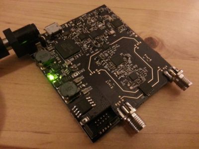
For more details: Cheap homemade 30 MHz – 6 GHz vector network analyzer