
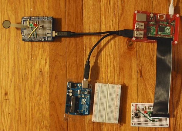
This instructable is a demonstration of the Drogon Remote Control (DRC) feature included with wiringPi.
Drogon Remote Control consists of an Arduino program that handles USB communication between the Arduino(s) and the RaspberryPi. I will be running two arduinos, with the same DRC sketch on both of them. It's like the RaspberryPi and the Arduino(s) become one, giving you the power of both, and all the programming is done on the RaspberryPi. You can download the Arduino Sketch Here:
https://projects.drogon.net/drogon-remote-control/drc-downloads/
The RaspberryPi program in this tutorial uses the wiringPi libraries, written by Gordon Henderson, for programming the GPIO in C.
wiringPi must be installed. Instructions for download, installation and use are located at http://wiringpi.com
wiringPi uses it's own pin numbering scheme.
All RaspberryPi pin numbers are wiringPi numbers unless otherwise specified.
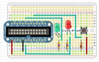
Step 1: The RaspberryPi Circuit
You will need a way to run wires from the RaspberryPi to the breadboard. You can use male/female jumper wires but one of the Pi Cobblers listed on this page from Adafruit will make it a lot easier: http://www.adafruit.com/search?q=cobbler
For the RaspberryP circuit you will also need:
- RaspberryPi
- Breadboard
- Jumper wires
- 2 – LEDs, I used one red and one green.
- 2 – 330-560 Ohm resistors, for the LEDs.
- 1 – Push button switch
- 1 – 10K resistor, pull-down resistor for switch.
Use these parts to copy the circuit in the illustration above.
You can get everything you need, except the resistors from Adafruit athttp://www.adafruit.com/
or at Sparkfun, https://www.sparkfun.com/
Sparkfun also carries a nice resistor assortment that includes 25 of every value of resistor you will ever need, you can find it herehttps://www.sparkfun.com/products/10969.
Step 2: The Arduino Circuit
The first Arduino makes use of pinMode(), digitalRead(), digitalWrite(), analogRead(), and pwmWrite() functions all called from the RaspberryPi. This is the easiest way I know of to add an analog to digital converter to the RaspberryPi. Notice that wiringPi uses pwmWrite instead of analogWrite, it's more accurate.
The second Arduino just blinks the built in LED on pin thirteen, completely under control of the RaspberryPi. This is just to show that it really can control multiple Arduinos. It also shows a good but simple use of wiringPi's ability to multi-thread.
If you only have one Arduino you can still try the program, step 5 will tell you which lines of the program to comment out.
I built the Arduino circuit on a prototyping shield but I show the circuit diagram on a breadboard for clarity.
For the Arduino circuit you will need:
- 2 – Arduinos
- 2 – USB cables to connect to the RaspberryPi
- Breadboard
- Jumper wires
- 2 – LEDs, I used one red and one green.
- 2 – 330-560 Ohm resistors, for the LEDs.
- 1 – Push button switch
- 1 – Resistive sensor
- 2 – 10K resistors, pull-downs for switch and sensor.
Use these parts to copy the circuit in the illustration above.
I used a force sensitive resistor for the resistive sensor, but a photo cell or a bend sensor will work just as well. You can also use a potentiometer. To wire a potentiometer forget the 10K resistor, wire the middle lead to the pin, one end lead to the positive rail and the other to ground.
Step 3: The Code
Download this program for your RaspberryPi.
Compile it with the command: gcc -o DRCtest DRCtest.c -lwiringPi -lpthread
/************************************************************************
 * DRCtest.c - Test program for Drogon Remote Control. (DRC)
 *
 * On the first Arduino:
 * LEDs are connected to pins nine and eleven, with 560 Ohm current limiting resistors.
 * A push button switch is connected to pin five, with a 10K pull-down resistor.
 * A resistive sensor is connected to analog pin zero, with a 10K pull-down resistor.
 * The only connection to the RaspberryPi is the USB cable.
 * The program in the RaspberryPi is controling the Arduino.
 * The DRC.ino program must be installed and running.
 *
 * Nothing is connected to the second Arduino.
 *
 * On the RaspberryPi:
 * LEDs are connected to pins nine and eleven, with 560 Ohm current limiting resistors.
 * A push button switch is connected to pin five, with a 10K pull-down resistor.
 * The pin numbers for the RaspberryPi use the wiringPi pin numbering scheme.
 *
 * The loop() function does a digitalRead of the push button on the Arduino
 * and digitalWrites the value to the both red LEDs
 * Next it performs an analogRead of the force sensitive resistor, divides
 * the value by four, and pwmWrites the value to both green LEDs.
 * Then is does a digitalRead of the push button on the RaspberryPi
 * and digitalWrites the value to the both red LEDs
 *
 ************************************************************************/
#include <stdio.h>
#include <wiringPi.h>
#include <drcserial.h>

#define    BASE    100
#define    BASE2    200
/*****************************************************************************
 * The second thread blinks the built in LED on pin 13 of the Second Arduino.
 * The code here runs concurrently with the main program in an infinite loop.
 *****************************************************************************/
PI_THREAD(arduino2)
{
  for(;;)
  {
    digitalWrite(BASE2+13, HIGH); // Turn pin 13 on.
    delay(500);
    digitalWrite(BASE2+13, LOW); // Turn pin 13 off.
    delay(500);
  }
}
/**************************************************************************
 * setup() function
 **************************************************************************/
void setup(void)
{
  wiringPiSetup();
  drcSetupSerial(BASE, 20, "/dev/ttyACM0", 115200);
  drcSetupSerial(BASE2, 20, "/dev/ttyACM1", 115200);

  int x = piThreadCreate(arduino2); // Start second thread.
  if (x != 0) printf("It didn't start.\n");

// Pins on Arduino:
  pinMode (BASE+11, PWM_OUTPUT);    // Reset pin to maximum value
  pwmWrite(BASE+11, 255);           // after PWM write.

  pinMode (BASE+5, INPUT);          // Pin 5 used for digitalRead.

  pinMode (BASE+9, PWM_OUTPUT);     // Pin 9 used for pwmWrite.
                                    // Pin A0 is used for analogRead.
// Pins on second Arduino:
  pinMode (BASE2+13, OUTPUT);       // Pin 13 used for digitalWrite.

// Pins on RaspberryPi:
  pinMode(0, OUTPUT);               // Pin 0 used for digitalWrite.
  pinMode(5, INPUT);                // Pin 5 used for digitalRead.

  pinMode(1, PWM_OUTPUT);           // Pin 1 used for pwmWrite.
}
/**************************************************************************
 * loop() function
 **************************************************************************/
void loop(void)
{
  digitalWrite(BASE+11, digitalRead(BASE+5)); // If Arduino button is pressed
  digitalWrite(0, digitalRead(BASE+5));       // turn on both red LEDs.

  pwmWrite(BASE+9, (analogRead(BASE)/4));     // Varies the brightness of both green
  pwmWrite(1, (analogRead(BASE)/4));          // LEDs according to pressure applied
                                              // to the force sensitive resistor.

  digitalWrite(BASE+11, digitalRead(5));      // If RaspberryPi button is pressed
  digitalWrite(0, digitalRead(5));            // turn on both red LEDs.
}
/**************************************************************************
 * main() function
 **************************************************************************/
int main (void)
{
  setup();
  for(;;)
  {
    loop();
  }
  return 0 ;
}
For more detail: Combine 1 or more Arduinos with a RaspberryPi