
Story
This project is part of Microsoft’s Hack the Home initiative, which provides makers with free, open-source components for effortless interfacing with the devices and services that makers use most to hack their homes.
This project shows how you can use the power and flexibility of the Raspberry Pi and Windows IoT core to recycle an existing device (in this case a Clock Radio) and extend its existing functionality using the power of an Internet Connected operating system.
Using the the universal Windows platform and IoT Core extensions you can quickly and easily interface with the existing controls on the device and this walk-through should provide you with the information required to reuse a clock radio device of your own or even extend the example to be used on different devices with more functionality.
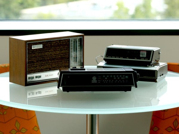
The aim of this project was to take a used clock radio, strip the original components out of the casing and mount a Raspberry Pi inside to make the device internet connected. The use of an existing device is not a requirement though, a simple internet radio device can be created by just following the wiring for the LCD and buttons (explained in the Hardware section) and then deploying the supplied application to your Pi (explained in the Software section) and a simple case could even be 3D printed.
I wanted to keep the device close in appearance to the original but change and expand the functionality to take advantage of the fact that it is now running a full, internet connected operating system.
Hardware
The first step in this project was to create a circuit that could replicate the original functionality of the device, interface with the Raspberry Pi's built in I/O circuits and fit into a case. The circuit I used to prototype during application development (and that was later soldered onto a prototype board for installation) is shown in the fritzing diagram below. This setup requires 11 individual GPIO pins (5 for the buttons and 6 for the LCD) but the actual pins chosen aren't significant and are configurable in the application source (as described later in the Application section).
The wiring setup for the radio is shown in the fritzing diagram below and the steps you can follow to setup this circuit are as follows (pin diagrams for the LCD and Raspberry pi can also be found below):
LCD Screen:
- Connect the GND, LED – and R/W pins of the LCD to a ground pin on the Raspberry Pi (I used pin 39).
- Connect the Vcc and LED + (sometimes also labeled as BL1) pins on the LCD to a 5v pin on the Raspberry Pi (I used pin 2).
- Connect the RS, EN, DB4, DB5, DB6 and DB7 pins on the LCD to GPIO pins on the Raspberry Pi (I used 18, 23, 24, 5, 6 and 13 respectively but these pins can be configured in the software later).
- Connect pin 1 of the 10k potentiometer to a 5v pin on the Raspberry Pi (I used pin 2).
- Connect pin 3 of the 10k potentiometer to a ground pin on the Raspberry Pi (I used pin 39).
- Connect pin 2 of the 10k potentiometer to the VEE (sometimes also labeled as V0) pin on the LCD (this controls contrast).
Buttons (repeat these steps for the amount of buttons you want in your project):
- Connect one end of the 330Ω resistor to a 5v pin on the Raspberry Pi (I used pin 2).
- Connect the other end of the 330Ω resistor to a PTM (push to make) button.
- Connect the other end of the PTM button to a ground pin on the Raspberry Pi (I used pin 39).
- Add a wire inbetween the resistor and the PTM button and connect it to a GPIO pin on the Raspberry Pi (I used 27, 22, 16, 12 and 4 for my buttons).
The sounds from the radio streams are played through the Pi's 3.5mm stereo out jack, to allow integration with the existing speaker in the case I chose I used a mono sound breakout board (as described later) but any speaker or headphones that have a 3.5mm plug can be connected to the Pi.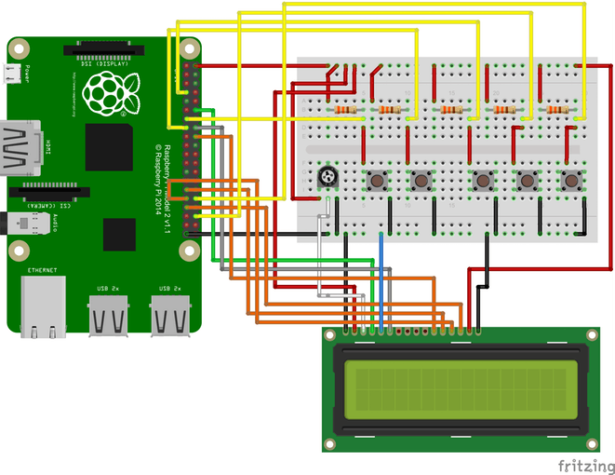
oftware
All of the code described below is available in the repository listed in the code section of this Hackster post so that you can easily deploy and extend it to fit your specific application.
For more detail: Connected Clock Radio