
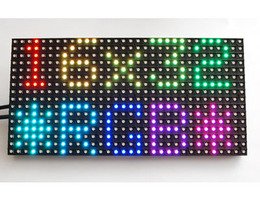
Overview
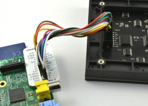
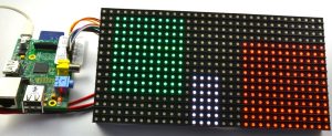
Wiring the Display
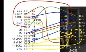
Note that the 3.3V and 5V pins of the Raspberry Pi are on the edge of the Raspberry Pi where the SD card fits!
If you prefer to make the connections using a list, they are as follow:
- GND on display to GND on the Pi (blue or black)
- R1 on display to GPIO 17 on the Pi (red)
- G1 on display to GPIO 18 on the Pi (green)
- B1 on display to GPIO 22 on the Pi (blue)
- R2 on display to GPIO 23 on the Pi (red)
- G2 on display to GPIO 24 on the Pi (green)
- B2 on display to GPIO 25 on the Pi (blue)
- A on display to GPIO 7 on the Pi (yellow or white)
- B on display to GPIO 8 on the Pi (yellow or white)
- C on display to GPIO 9 on the Pi (yellow or white)
- OE on display to GPIO 2 on the Pi (brown)
- CLK on display to GPIO 3 on the Pi (orange)
- LAT on display to GPIO 4 on the Pi (yellow)
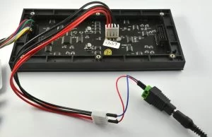
When all the data pins are connected, we can wire up the power supply.
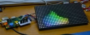
Testing
Before powering up the Display and Raspberry Pi, check the wiring over carefully and make sure everything is connected as it should be.
- $ mkdir display16x32
- $ cd display16x32
- $ git clone https://github.com/hzeller/rpi-rgb-led-matrix/
- $ cd rpi–rgb–led–matrix
- $ make
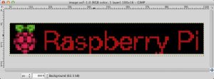
A Scrolling Message
The images must be in a format called ppm (portable pixel format). Many image editors support this format, including the free open source application Gimp.
Run the command again, this time using the name that you gave the file:
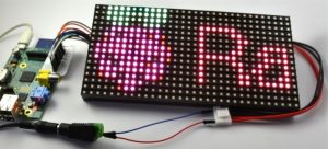
- $ sudo ./led–matrix 1 my_image.ppm
Experimental Python Code
As an experiment, I decided to see how practical it would be to try and drive the display from Python code, rather than using the much faster C code.
I had fairly limited success in this. The display refreshes with a bit of flicker, is rather uneven in light intensity and dimmer than the C code. So if anyone can improve the code and make it work better, we would love to hear from you and be happy to update this section with due credit.
If you want to give it a go, the wiring is exactly the same as before, and you will just need to paste the following code into a file called test_display.py
import RPi.GPIO as GPIO
import time
delay = 0.000001
GPIO.setmode(GPIO.BCM)
red1_pin = 17
green1_pin = 18
blue1_pin = 22
red2_pin = 23
green2_pin = 24
blue2_pin = 25
clock_pin = 3
a_pin = 7
b_pin = 8
c_pin = 9
latch_pin = 4
oe_pin = 2
GPIO.setup(red1_pin, GPIO.OUT)
GPIO.setup(green1_pin, GPIO.OUT)
GPIO.setup(blue1_pin, GPIO.OUT)
GPIO.setup(red2_pin, GPIO.OUT)
GPIO.setup(green2_pin, GPIO.OUT)
GPIO.setup(blue2_pin, GPIO.OUT)
GPIO.setup(clock_pin, GPIO.OUT)
GPIO.setup(a_pin, GPIO.OUT)
GPIO.setup(b_pin, GPIO.OUT)
GPIO.setup(c_pin, GPIO.OUT)
GPIO.setup(latch_pin, GPIO.OUT)
GPIO.setup(oe_pin, GPIO.OUT)
screen = [[0 for x in xrange(32)] for x in xrange(16)]
def clock():
GPIO.output(clock_pin, 1)
GPIO.output(clock_pin, 0)
def latch():
GPIO.output(latch_pin, 1)
GPIO.output(latch_pin, 0)
def bits_from_int(x):
a_bit = x & 1
b_bit = x & 2
c_bit = x & 4
return (a_bit, b_bit, c_bit)
def set_row(row):
#time.sleep(delay)
a_bit, b_bit, c_bit = bits_from_int(row)
GPIO.output(a_pin, a_bit)
GPIO.output(b_pin, b_bit)
GPIO.output(c_pin, c_bit)
#time.sleep(delay)
def set_color_top(color):
#time.sleep(delay)
red, green, blue = bits_from_int(color)
GPIO.output(red1_pin, red)
GPIO.output(green1_pin, green)
GPIO.output(blue1_pin, blue)
#time.sleep(delay)
def set_color_bottom(color):
#time.sleep(delay)
red, green, blue = bits_from_int(color)
GPIO.output(red2_pin, red)
GPIO.output(green2_pin, green)
GPIO.output(blue2_pin, blue)
#time.sleep(delay)
def refresh():
for row in range(8):
GPIO.output(oe_pin, 1)
set_color_top(0)
set_row(row)
#time.sleep(delay)
for col in range(32):
set_color_top(screen[row][col])
set_color_bottom(screen[row+8][col])
clock()
#GPIO.output(oe_pin, 0)
latch()
GPIO.output(oe_pin, 0)
time.sleep(delay)
def fill_rectangle(x1, y1, x2, y2, color):
for x in range(x1, x2):
for y in range(y1, y2):
screen[y][x] = color
def set_pixel(x, y, color):
screen[y][x] = color
fill_rectangle(0, 0, 12, 12, 1)
fill_rectangle(20, 4, 30, 15, 2)
fill_rectangle(15, 0, 19, 7, 7)
while True:
refresh()
Looking at the end of the file, you can see the “fill_rectangle” and “set_pixel” functions that you can use to draw on the screen. The final argument of both of these functions is the color that should be a number between 0 and 7.
The display refreshing should really take place in a separate thread of execution, but as I said, this is more of an experiment than anything else.