
In a previous post, I described my idea of a universal console with the Raspberry Pi. I presented, what I called, the SNESDev-RPi, which is an SNES-controller interface for the Raspberry Pi. A core element of this interface is a SNES-adapter PCB that I recently designed and that does nothing more than providing all needed connections between the GPIO pins and two SNES connectors. In this post I describe the details for assembling the SNES-adapter that I showed in the previous post. Furthermore, I show how a single SNES socket can be directly connected to the GPIO pins of the Raspberry Pi.
This post is organized in two sections: The first section describes the details for assembling the SNES adapter with the PCB. The second section describes, how a single SNES socket can directly be connected to the Raspberry Pi.
 Before I begin with the descriptions I want to say that both described approaches need soldering and work with heat and electricity. This means that you should know what you are doing when following these instructions!
Assembling the SNES adapter with the PCB
In this section I describe how to connect two SNES connectors to the SNES-adapter PCB that I recently designed. The PCB replaces some wires and makes it easily possible to attach two SNES connectors to the Raspberry Pi.
For the assembly we need the following components:
-
- 1x SNES-adapter PCB
- Ribbon cable – 26 wire
- Ribbon Cable – 6 wire (from which we only use five wires)
- 1x Ribbon Crimp Connector, 2×13 pins
- 2x SNES connectors (I got these from two extension cables for SNES controllers)
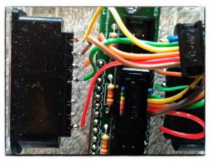
As you might have noticed I left out the shrouded pin headers used for the prototype as shown in the previous post. I realized that these take quite a lot of space. To allow for putting the whole adapter into a nice small case I decided to discard them here. The assembly consists mainly of dismantling the wires and soldering them to the pins and pads.
Here is a diagram that illustrates all needed connections between the connectors and the PCB (tap to show it in large). To be on the safe side, use pin 1, which provides 3.3V! According to other sources the polling of the SNES controller should also work with 3.3V.
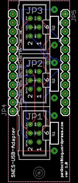 The red lines illustrate the connections between the GPIO connector and the PCB. Here I chose those GPIO pins that are used in the SNESDev-RPi implementation. The connections between the SNES connectors and the PCB are indicated by pairs of numbers or capital letters and are shown in purple.
For the sake of completeness also the pin out for two optional LEDs and a button is shown. A button can be attached between the “b”s. An LED can be attached (watch the polarization!) between “n” and “GND” or “m” and “GND”, respectively. As already mentioned, the LEDs and the button are not used here. But if you want to use them, you also have to connect the LED and BTN pins on the left of the PCB to the GPIO connector. Also, you need to solder three resistors on the boad to make the circuits work. I used 2.2k Ohm 1/4W resistors, but similar ones would also do here.
For more detail: Connecting SNES sockets to the Raspberry Pi: An assembly guide