| Hardware components: | ||||||
 |
|
× | 1 | |||
 |
|
× | 1 |
 |
|
× | 1 | |||
 |
|
× | 1 | |||
 |
|
× | 1 |
Story 
This is a basic project to connect an LED to RPi GPIO and control using a python script.
Step 1: Components
You'll need the following components to connect the circuit.
1. Raspberry Pi2. LED3. Resistor – 330 ohm4. Breadboard5. 2 Male-Female Jumper Wires
Except for the Raspberry Pi, you can buy a basic starter kit which will include all the other components.
Step 2: Connecting the Circuit
Please keep the Raspberry Pi turned off until the circuit is connected to avoid accidentally shorting any components.
The LED has 2 legs. The longer leg, ‘anode', is always connected to positive supply. The shorter leg,'cathode', is always connected to ground.You need a resistor is the circuit to limit the amount of current in the circuit. Without the resistor the current flowing through the LED will be much larger and lead to a short damaging the circuit.You can identify a 330 Ohm resistor using the color coding on the resistor:
- If there are four colour bands, they will be Orange, Orange, Brown, and then Gold.
- If there are five bands, then the colours will be Orange, Orange, Black, Black, Brown.
Connect the circuit:
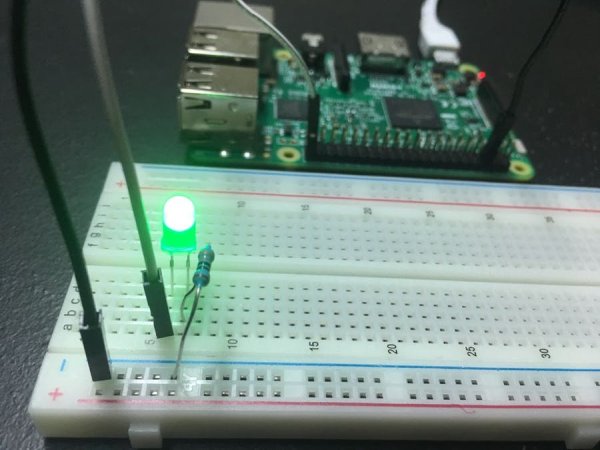
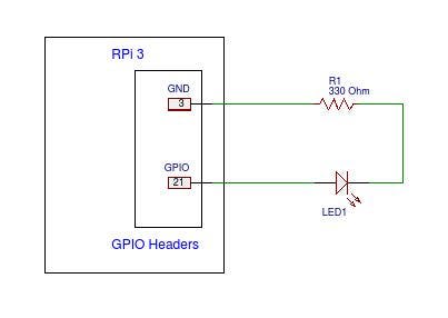
- Use a jumper wire to connect the ground ( Pin 3) of GPIO to rail marked in blue on the breadboard.
- Connect the resistor from the same row on the breadboard to a column on the breadboard.
- Connect the LED with the cathode in the same row as the resistor. Insert the anode in the adjacent row.
- Use another jumper cable to connect the GPIO Pin 21 ( 3.3 V) in the same row as the anode of LED.
This completes the circuit. Refer to the picture and the schematic above.
For more detail: Control LED Using Raspberry Pi GPIO


