
Assembly
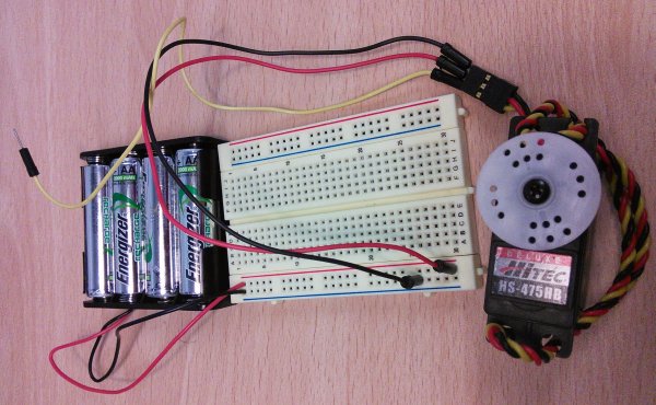
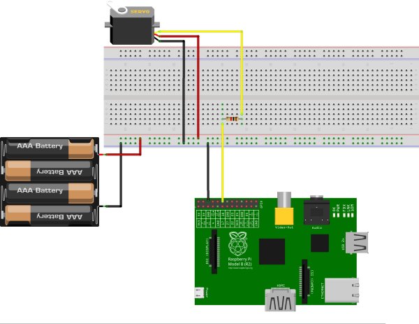
The servo motors have three pins, two for power: red(+) and black (-), and one for control. Because the servo motor draws too much energy, we need to use the batteries to power the servo (the Raspberry Pi doesn't have so much power. if you try to use the 5V power of the raspberry pi, you may freeze your Raspberry Pi).
The red (+) of the batteries are connected to the red (+) cable of the servo, and the black (-) of the batteries are connected to the black (-) of the servo AND to the ground (-) of the Raspberry Pi. The yellow wire of the servo is connected to the resistor and the resistor is connected to the GPIO pin 1 of the Pi.
 Just like in the previous tutorial, each of the yellow boxes in the BlueJ screen above is a Java class. The Servo_motor class represents a real servo motor connected to the Raspberry Pi.
The Controller class is a skeleton class which we will be using in this tutorial to contain code which will control ServoMotor objects.
Creating a new ServoMotor object
Before we start to write code, we'll see how the ServoMotor class affects the real servo motor by using BlueJ to control it directly.
BlueJ will ask for the “name of the instance”: the suggested name is good for now. You will see a red rectangle on the bottom left of the BlueJ window named “adjustab1.
 This rectangular red icon represents the “servoMot1” object. This object is the Java representation of the real servo motor connected to the Raspberry Pi.
Changing position of the servo motor
The servo motor has 20 possible positions, represented by integers from 0 to 20, inclusive. To set the ServoMotor to any of those positions.
For more detail: Controlling a Servo Motor