This tutorial demonstrates how to attach a LED to the expansion connector on your Raspberry PI and to make it blink with a simple C++ program.
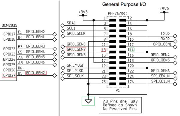
- First of all, in order to programmatically switch a LED on and off we need to connect it between a general-purpose input/output pin (GPIO) and the ground. Then we need to change the state of the pin between 1 and 0 to switch the LED on and off. The basic schematics is depicted below:

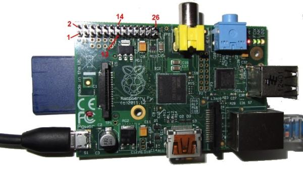
According to the schematics above, pin #13 corresponds to a software-controllable GPIO27 and pin #14. Here's how this looks on the board:
We will now connect our external LED with a resistor to pins 13 and 14 of the connector P1. This requires soldering together a LED, a resistor and a pair of connectors compatible with P1 pins:
- Warning! Mishandling things while or after soldering may burn your Raspberry PI and even your PC connected to it via USB! We assume no liability for any damages related to following or misfollowing this tutorial. If you still feel like experimenting, do not solder anything on a circuit that is currently powered or connected to a powered device. Be careful when connecting things, as short-circuiting certain pins will restart (and might even burn) our board and any devices attached to it. Use an expandable USB phone charger instead of your actual computer as the power source.
- Turn off your Raspberry PI board and carefully connect the LED to the P1 header. Ensure that you have not short-circuited any adjacent pins. Use a multimeter to be 100% sure. When done all checks, turn it on:
For more detail: Creating a Blinking LED project for Raspberry PI


