
Raspberry Pi is an ARM architecture processor based board designed for electronic engineers and hobbyists. The PI is one of most trusted project development platforms out there now. With higher processor speed and 1 GB RAM, the PI can be used for many high profile projects like Image processing and Internet of Things.
For doing any of high profile projects, one need to understand the basic functions of PI. We will be covering all the basic functionalities of Raspberry Pi in these tutorials. In each tutorial we will discuss one of functions of PI. By the end of tutorial series you will be able to do high profile projects by yourself. Check these for Getting Started with Raspberry Pi and Raspberry Pi Configuration.
We have discussed LED Blinky, Button Interfacing and PWM generation in previous tutorials. In this tutorial we will Control the Speed of a DC motor using Raspberry Pi and PWM technique. PWM (Pulse Width Modulation) is a method used for getting variable voltage out of constant power source. We have discussed about PWM in the previous tutorial.
There are 40 GPIO output pins in Raspberry Pi 2. But out of 40, only 26 GPIO pins (GPIO2 to GPIO27) can be programmed. Some of these pins perform some special functions. With special GPIO put aside, we have 17 GPIO remaining. To know more about GPIO pins, go through: LED Blinking with Raspberry Pi
Each of these 17 GPIO pin can deliver a maximum of 15mA. And the sum of currents from all GPIO Pins cannot exceed 50mA. So we can draw a maximum of 3mA in average from each of these GPIO pins. So one should not tamper with these things unless you know what you are doing.
There are +5V (Pin 2 & 4) and +3.3V (Pin 1 & 17) power output pins on the board for connecting other modules and sensors. This power rail is connected in parallel to processor power. So drawing High current from this power rail affects the Processor. There is a fuse on the PI board which will trip once you apply high load. You can draw 100mA safely from the +3.3V rail. We are talking about this here because; we are connecting the DC motor to +3.3V. With the power limit in mind, we can only connect low power motor here, if you want to drive high power motor, consider powering it from a separate power source.
Components Required:
Here we are using Raspberry Pi 2 Model B with Raspbian Jessie OS. All the basic Hardware and Software requirements are previously discussed, you can look it up in the Raspberry Pi Introduction, other than that we need:
- Connecting pins
- 220Ω or 1KΩresistor (3)
- Small DC Motor
- Buttons (2)
- 2N2222 Transistor
- 1N4007 Diode
- Capacitor- 1000uF
- Bread Board
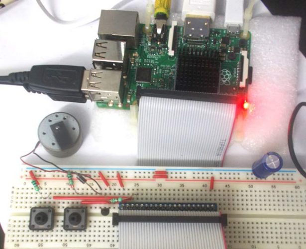
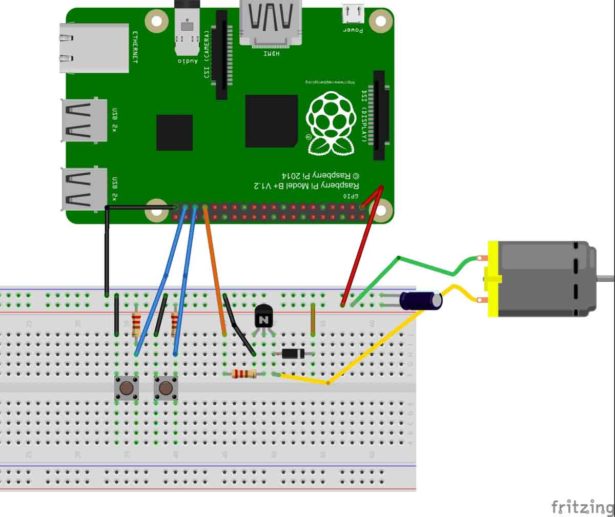
Circuit Explanation:
For more detail: DC Motor Control with Raspberry Pi