The Raspberry Pi is an amazing device. Although not the most powerful mini computer out there, it bolsters a tremendous support community, tons of hardware add-ons and coding libraries to your heart’s desire. The Raspberry Pi also makes an affordable media player but so much more can be done with it. In this post, I’ll try to show you how I turned your typical Raspberry Pi, combined with some cheap components and IP Cameras, into a state-of-the-art home monitoring system capable of recording video, turning power outlets on or off and sensing movement.
Some time ago, I bought a couple of your run-of-the-mill entry level IP cameras. I’m sure you’ve seen them. They can be had for $50 to $100, are feature packed, and able to connect to your home network via Wifi or Ethernet. However, I’ve always had issues with the built-in motion sensing feature which seems to be affected quite easily based on the changing lighting conditions. After numerous false positives, I’ve decide to take matters in my own hands. It snowballed…this is the end result.
Key Features
- Displays live feed and records to a local or network disk from two IP cameras
- Controls two wireless power outlets/switches
- Able to sense motion and trigger sending of emails (SMS to cell phone), snapshots and recording
- Can be scheduled via a simple interface
- Displays temperature/humidity
Camera Setup
For the camera setup, I connect the camera via Ethernet on my LAN and simply configure a static IP address, a gmail account and turn on the Motion Detection Alarmed as a fail safe (even though I will use a PIR sensor). Also, I created an additional administrator account through the interface.
Raspberry Pi GPIO
What make the Raspberry Pi so versatile is that it comes with a set of input/output pins, more specifically:
The Raspberry Pi has a 26-pin General Purpose Input/Output (GPIO) connector that carries a set of signals and buses. There are 8 general purpose digital I/O pins – these can be programmed as either digital outputs or inputs. One of these pins can be designated for PWM output too. Additionally there is a 2-wire I2C interface and a 4-wire SPI interface (with a 2nd select line, making it 5 pins in total) and the serial UART with a further 2 pins.
If you didn’t quite understand that, it’s all ok, ’cause neither did I. What you really need to know is how to identify the pins, as this is where we will be connecting the sensors.
PIR Sensor
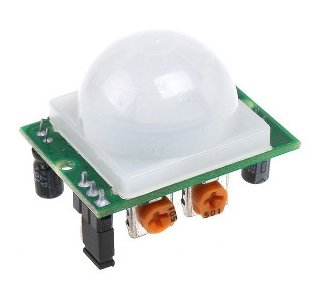
The first sensor we’ll connect is a PIR sensor and can be purchased on Ebay quite cheaply. The PIR sensor is a motion sensor and has 3 pins. In fact, hooking it up to your Raspberry Pi, assuming you have jumper wires, couldn’t be any easier. It requires no soldering nor any additional components.
When researching how to incorporate the PIR sensor with the Raspberry Pi, I came across this post. The author even provides some Python code which I used as a template for my own Python script.
In short, I added some functionality to the script – which quite honestly, wasn’t that hard to do. Now, when the PIR sensor is tripped the following happens:
- Arms the camera (that is, it turns on the option Send Mail on Alarm on the camera)
- Sends an email to both my personal email and to my phone via the email address phone_number@phone_provider
- Kicks off a recording from a specified camera to a local or networked disk via ffmpeg
This is all configurable in the configuration file and triggered via the PIR Alarm button on the UI.
Please take a look at the code in:
/bin/pir/pir.py |
 Permissions
Unfortunately, the pir.sh script (that’s kicks off the pir.py script) needs sudo to run, because of this, the www-data user needs the appropriate rights. I know, totally insecure to do this, but since the project resides on an internal LAN, I’m not worried.
|
1
2
3
|
sudo visudo(add)www-data ALL=NOPASSWD: /{PATH_TO_WWW}/mypihc/bin/pir/pir.sh |
Compile ffmpeg
You will need the latest version of ffmpeg installed on the Raspberry Pi. Unfortunately, I had to compile mine from source code, which isn’t too hard to do but could take hours!
As I said before, I use ffmpeg to handle the recording from the camera to disk. It’s a fool proof way to produce a manageable video file.
|
1
2
3
4
5
|
Once complete you should have the ffmpeg binary in:
/usr/local/bin/ffmpeg |
433MHz Transmitter/Receiver
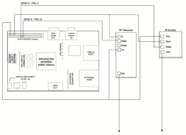
Another rather cool component is the 433MHz Transmitter/Receiver which again, is relatively inexpensive and easy to connect to your Raspberry Pi. The reason for this is that I’d like to be able to control the power outlets such that I could turn on/off devices via a script or web interface instead of always using the included remote. These buttons are labelled Switch A / Switch B on the page.
For more detail: DIY Alarm Monitoring System w/ Raspberry Pi + Foscam + Sensors


 Permissions