
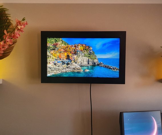
The idea behind this project was to build a large digital picture frame at a lower cost than the ones you could purchase. It needed to be easy to build and operate smoothly. I concentrated on setting up the computer/software side first before building a wooden frame and mounting the monitor to the wall.
The project was built on a Raspberry Pi 3 Model A+. It also incorporated a light sensor that adjusted the brightness of the monitor depending on the brightness of the room. Lastly, I expanded the project with a touch sensor to safely shut down the Raspberry Pi and provide additional functionality.
I have written the instructions in a modular way so that you only need to complete the parts you require, for example, the light sensor, touch sensor, and frame are optional. I have also included a section at the end of unsuccessful software choices if you are considering other options in this space.
Credit
Wallpapers thanks to: https://www.pexels.com/@pixabay
Music: L'Outlander – City On A Hill, provided by Lofi Girl
Why I built it this way
There were a number of lessons learned in getting to the final project build.
- Linux setup needed to be simple. I come from a Windows OS background so my Linux expertise is minimal
- Previous attempts to build a digital picture frame from a laptop failed miserably. Mounting a dismantled laptop into a picture frame was a nightmare, having to access ports was another disaster, etc
- Using the existing VESA mounting brackets on the monitor to attach to the wall meant I did not have to engineer a frame that would have to support the monitor's weight
- The monitor needed to support DDC/CI for brightness control over HDMI, provide power to the Raspberry Pi via USB (less cables up the wall), and having an ultrathin bezel made building a frame a lot easier
- PiicoDev sensors were used as they offered a near plug and play usability
- FBI software could be launched from Terminal, so there was no need for an OS GUI
Supplies
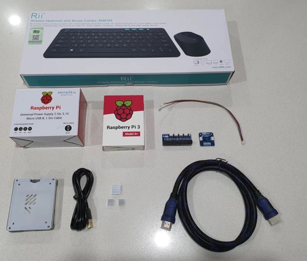
The hardware I ended up using
- Dell P2422H Monitor
From Core Electronics
- Raspberry Pi 3 Model A+
- Case – Pimoroni Pibow 3 A+ Coupé Ninja
- 3pc Heatsink Kit for Raspberry Pi 4 (I only used the 1 Heatsink for the CPU)
- High-speed HDMI cable (3 feet)
- Micro USB cable (to power the unit from the monitor)
- PiicoDev Adapter for Raspberry Pi
- 2x PiicoDev cable 200MM
- PiicoDev Ambient Light Sensor VEML6030
- PiicoDev Capacitive Touch Sensor
- Hook-up stranded wire – white (22 AWG)
From Amazon
- SanDisk 32GB Ultra microSDHC UHS-I Memory Card
- LCD Wall Mount Bracket
Bunnings (Hardware Store)
- x2 Pine Dressed Standard Grade 42X19MM 1.2M
- Ramset Super Wallmate Toggle Anchor (Hollow Wall Anchors)
- Plasterboard Masonry Wall Hook – 5 Pack
Hardware that I could have done without, but used anyway
- Small wireless keyboard and mouse combo
- Raspberry Pi 3 + power supply (Official)
Tools
- Tenon Saw
- Mitre Box
- Ruler
- Chisel
- Hammer
- Sandpaper
- Paint
- Wood filler
- Clamps
- Router
- Cove bit: 5mm radius
- Screwdrivers (various)
- Soldering iron and solder
- Wire cutters
- Utility knife
Step 1: Installing the Operating System
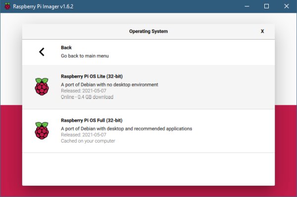
To install the OS you need to image an SD card. Simple instructions and the download can be found here. I ended up installing the Raspberry Pi OS Lite (32-bit) with no desktop environment as I wanted to keep it snappy.
Using the shortcut CTRL + SHIFT + X when setting up in the Raspberry Pi Imager will allow you to set up a Hostname, configure Wi-Fi, enable ssh and a password, and other local settings (there is also a 45-second video on this page).
Step 2: Case and Heatsink
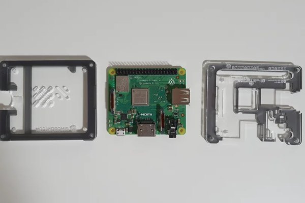
Fitting a case was a top priority to protect the Raspberry Pi from any mishaps. I used the Pimoroni Pibow case as it had room to access the GPIO header and still attach the heatsink. The case came with instructions in the form of a YouTube link which made assembly easy.
Attaching the heatsink was as easy as peeling back the tape on the flat side and applying it to the Raspberry Pi.
Step 3: Slideshow Software Setup
Connect the Raspberry Pi up to your keyboard, monitor, and power. Once you get to the login screen enter your credentials. The default username is “pi” and the password is generally the one set up in Raspberry Pi Imager earlier under ssh.
You should also have network/internet access if you entered in your Wi-Fi details earlier. Let's now update the Raspberry Pi OS. At the terminal enter:
sudo apt-get update && sudo apt-get upgrade
The “sudo” part of the command allows you to run programs with security privileges, as with “Run as Administrator” in Windows.
Once that is completed we need to install FBI.
FBI install
At the terminal enter:
sudo apt-get install fbi
FBI is now installed, how easy was that!
Copy over some pictures
Let's make a directory/folder, I was still under /home/pi so I typed in:
mkdir pictures
- to determine the location of the current directory type: PWD
- to list the files and folders that are in your current directory you need to type: ls
It's easy to move files from your Windows PC to your Raspberry Pi using the command SCP on your windows machine. First, you will need to know the IP address of Raspberry Pi, so at the terminal type:
ifconfig
Now on your Windows PC, from the command prompt, you will need to enter in a command similar to the below, using the path location where you saved your pictures and the IP address you got from the ifconfig step above.
scp C:/Users/username/OneDrive/Pictures/wallpapers/* [email protected]:/home/pi/pictures
It will prompt you for the Raspberry Pi password, then it will copy everything over from the folder specified.
FYI: later in this guide we will set a static IP address if required.
Testing FBI
Now is a good time to test to make sure that the FBI is working and to start experimenting with the command-line options. All these command-line options can be found in the reference material at the bottom of this step.
First, navigate into the pictures directory on the Raspberry Pi:
cd pictures
then type in:
fbi -a -t 5 *.jpg
This should cycle through your jpg images, changing every 5 seconds.
I ended up using the below command in my automatic startup script:
fbi -a -u --noverbose -blend 1000 -t 60 /home/pi/pictures/*
Reference material
Raspberry Pi Slideshow: https://github.com/lee2sman/rasp-pi-slideshow
Copy a file from Windows to Linux: https://bharatdwarkani.medium.com/copying-a-file-from-windows-to-linux-through-ssh-17f4f4c2eca8
Install and use FBI: https://www.raspberrypi-spy.co.uk/2017/02/how-to-display-images-on-raspbian-command-line-with-fbi/
Step 4: Setup Screen Resolution
You may have found your terminal window (and therefore your pictures) aren't running at the correct resolution, maybe even running in a letterbox on your monitor. So let's configure the screen resolution:
sudo raspi-config
Under “display options” than “resolutions” select the correct resolution that your TV or monitor supports.
You will notice that the list is split under DMT and CEA.
- CEA stands for Consumer Electronics Association and is the display standard that is typically used on a TV
- DMT stands for Display Monitor Timings and is the standard that is typically used by monitors
Select the correct one relating to your monitor. Restart and test FBI again to make sure you're happy with the results.
Step 5: Auto Launch Fbi on Startup
Auto login
First, we need to automatically log in to the command line. This can be set up in the Raspberry Pi configuration tool under System Options” > “Boot / Auto Login” > Console Autologin
sudo raspi-config
Auto start FBI
I added the FBI launch command we created earlier under a file called .bashrc. To edit .bashrc run the command:
nano ~/.bashrc
Then scroll down to the very bottom and add-in:
fbi -a -u --noverbose -blend 1000 -t 60 /home/pi/pictures/*
“Ctrl + x” to exit and press “y” to save.
Now restart your Raspberry Pi and you should have a working Digital Picture Frame.
Reference material
Automatically login: https://www.digikey.com.au/en/maker/blogs/2018/how-to-boot-to-command-line-and-ssh-on-raspberry-pi
Auto start FBI: https://forums.raspberrypi.com/viewtopic.php?t=168122
Step 6: Auto Adjust Monitor Brightness
This step is not a tutorial but a guide. What we want to achieve is to compile ddcutil so we can issue terminal commands to change the brightness on the external monitor, eg: just like pressing the buttons on the monitor but in this case, the software controls these actions.
Before heading down this path make sure your monitor supports this feature DDC/CI. In Windows, you can install an application called “Monitoring” from the Microsoft store to test that it can work.
Compile ddcutil by downloading the source and following the instructions on here http://www.ddcutil.com/building/. I was able to apt-get install all the dependencies listed on that page (remember to install the -dev versions). I kept installing packages listed on that page until ./configure ran.
Also, make the changes to /boot/config.txt specified at http://www.ddcutil.com/raspberry/ and reboot. I needed to add:
dtparam=i2c2_iknowwhatimdoing
After rebooting, I was able to set the brightness of my monitor using the command:
ddcutil setvcp 10 xx
where xx is a number from 0-100.
If you can get that working, sending some bash commands using values from the light sensor in the next section is easy.
Reference material
Monitoring: https://github.com/emoacht/Monitorian
Guide copied from forum post: https://forums.raspberrypi.com/viewtopic.php?t=145894
Instructions for compiling ddcutil: http://www.ddcutil.com/building/
Step 7: Light Sensor Setup and Testing
The PiicoDev Ambient Light Sensor was easy enough to plug in (see Reference material), but getting the module installed and running from the command line was not as straightforward for me. Again, this is more of a guide rather than a tutorial.
You will need to enable i2c, to do this from the command prompt you will need to run the configuration tool and find the enable selection in the menus:
sudo raspi-config
I also had some issues with i2c loading so I first had to check that i2c loads.
I had to add “i2c_dev” into “/etc/modules”
nano /etc/modules
then add in:
i2c_dev
“Ctrl + x” to exit and press “y” to save.
Python
You will also need to install Python to run the example script and PIP3 to install the Ambient Light Sensor modules.
When running the test script from core-electronics I had a lot of issues with different Python versions. What helped was checking if my module was installed using:
pip list
And found out that the module was installed under python 3, therefore instead of running:
python main.py
I needed to run:
python3 main.py
Once the example script was running and I was getting light readings I moved on to re-writing the example script and getting it to issue bash commands (see Step 8).
Reference material
Ambient Light Sensor: https://core-electronics.com.au/tutorials/piicodev-ambient-light-sensor-veml6030-raspberry-pi-guide.html
PIP: https://docs.python.org/3/installing/index.html
i2c Loading: https://raspberrypi.stackexchange.com/questions/1190/how-to-make-raspbian-load-the-i2c-dev-module-on-boot-up
Step 8: Light Sensor Brightness Code
The original example script was then modified, This was my first time writing a Python script so please excuse my bad code!
Code explanation
Every ~5 seconds “light Val” will be populated with a lux reading.
I wrote the script to have 4 different levels of brightness, from 0 to 75 (I did not go above 75 as my monitor would display a warning message about power consumption).
I wrote the script to only issue a command to change the monitor brightness if the level changed, so that's why it checks if the state is not equal to the last state before issuing the command.
# PiicoDev VEML6030 minimal example code
# This program reads light data from the PiicoDev VEML6030 ambient light sensor
# and displays the result

from PiicoDev_VEML6030 import PiicoDev_VEML6030
from time import sleep
import os

# Initialise Sensor
light = PiicoDev_VEML6030()

state = 4
lastState = 4

while True:
  # Read and print light data
  lightVal = light.read()
#  print(str(lightVal) + " lux")

  if lightVal < 20:
   state = 1
  elif lightVal < 75:
   state = 2
  elif lightVal < 140:
   state = 3
  else:
   state = 4

  if state != lastState:
    if state == 1:
    os.system("ddcutil setvcp 10 0")
    elif state == 2:
    os.system("ddcutil setvcp 10 25")
    elif state == 3:
    os.system("ddcutil setvcp 10 50")
    else:
    os.system("ddcutil setvcp 10 75")

  lastState = state

  sleep(5)
Once tested I then configured the script to run on startup (next step).
Note: Your final installation will require you to adjust the lux change values for your room, I also renamed main.py to light.py later in the project.
Step 9: Run Python Script on Startup
The Python script needs to be run on startup and in the background. I decided to run this in .bashrc
nano ~/.bashrc
and added the line above my last
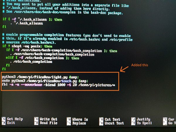
python3 /home/pi/PiicoDev/main.py &
Note: A final screenshot of .bashrc is located under step 11: PiicoDev Capacitive Touch Sensor
Step 10: Set a Static IP
I probably should have done this earlier, but you will want to set a static IP for your Digital Picture Frame, this will allow you to easily transfer pictures or art using the command “SCP” from windows in the future.
To do this you will need to edit dhcpcd.conf
sudo nano /etc/dhcpcd.conf
As I am using a wireless network connection (Raspberry Pi 3 Model A+ only has Wi-Fi built-in) I need to add/edit “wlan0”.
In dhcpcd.conf I added the static wireless IP details after the “Example static IP configuration” for eth0.
interface wlan0
static ip_address=192.168.0.14/24
static routers=192.168.0.1
static domain_name_servers=8.8.8.8
FYI: default gateway is set using “static routers”.
When completed, Ctrl + X to exit and Y to save.
Then reboot and make sure your changes have been made using ifconfig.
ifconfig
It might also be a good idea to ping a website to make sure you haven't broken anything!
Step 11: PiicoDev Capacitive Touch Sensor
Adding the PiicoDev Capacitive Touch Sensor was an afterthought when I realized I wanted to be able to safely shut down the Raspberry Pi, and what better and easy way than to add another PiicoDev Sensor!
The advantage of adding the PiicoDev Sensor was in addition to adding the shutdown button, the additional two buttons allowed me to add functionality to show the next image or show the previous image.
I realized I had already installed the Python modules required to run the Touch Sensor (see Light Sensor step), so I downloaded the example script, tested and then started editing.
Setup
Show next or previous image in FBI is controlled by pressing “page up” and “page down” on the keyboard, to simulate keyboard presses I install a module called keyboard for python:
pip install keyboard
Here is the final code. I needed to import the “os” module so I could send the shutdown command and of course the keyboard module so I could simulate page up and page down. In the final build, I needed to change the sensitivity as the additional length of wire made the touch sensor very sensitive. Check out the reference material for more info.
# PiicoDev Capacitive Touch Sensor CAP1203 demo code
# Read the touch sensor buttons and print the result

import os, keyboard
from PiicoDev_CAP1203 import PiicoDev_CAP1203
from PiicoDev_Unified import sleep_ms # cross-platform-compatible sleep

touchSensor = PiicoDev_CAP1203(touchmode="single",sensitivity=6)

while True:
  # Example: Display touch-pad statuses
  status = touchSensor.read()
  #print("Touch Pad Status: " + str(status[1]) + " " + str(status[2]) + " " + str(status[3]))
  if status[1] == 1:
   keyboard.press_and_release('page up')
  if status[2] == 1:
   keyboard.press_and_release('page down')
  if status[3] == 1:
   os.system("shutdown -h now")

  sleep_ms(100)
When running and testing this script, the keyboard module will require you to run as sudo
sudo python3 touch.py
Auto start Touch Sensor script
Add this to launch at startup by editing .bashrc. To edit .bashrc run the command:
nano ~/.bashrc
Then add the following line below the light script, see the photo attached to this step for my final edit of .bashrc
sudo python3 /home/pi/PiicoDev/touch.py &
Press “Ctrl + x” to exit and press “y” to save.
Step 12: Wall Mount

I decided to mount the monitor to the wall using a VESA mount, this would allow secure mounting of the monitor (the heaviest part, with the wooden frame just being attached to the monitor in the next step.
There are many choices of VESA mounts, just make sure you leave enough room for the Raspberry Pi at the back.
Ideally, I would have liked to mount the monitor a little closer to the wall, but I choose this mount as I could easily take the monitor off and on the wall for any future adjustments.
Step 13: Wooden Frame
To make it look more like a picture frame and not just a monitor mounted to the wall I added a wooden frame around the monitor.
This needed to be as simple as possible, so from the start of this project, the decision was for the monitor to hold the “fake” wooden frame, not for the frame to hold the monitor. This would then allow me to mount the monitor to the wall using a VESA mount.
The picture frame was made with the tools I had available. If you are fortunate enough to have additional tools, this would make the build a lot easier.
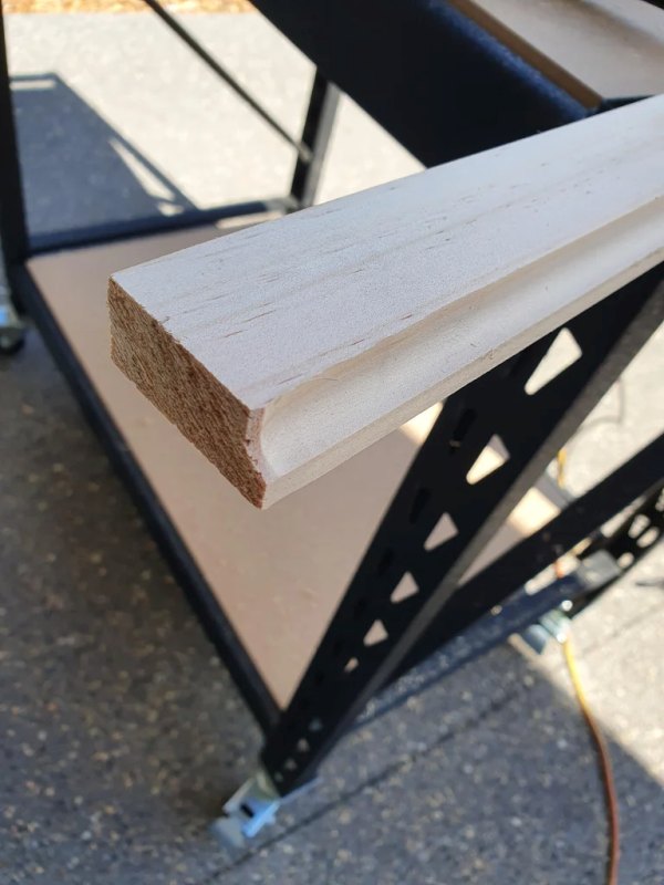
- The pinewood was first routered with the cove bit, 5mm radius
- The two lengths of pine were then measured and cut at a 45 degrees angle using the Miter Box
- I needed to chisel out what would be the bottom section of the frame (where I previously routed) to allow for the larger bezel part on the bottom of the monitor.
- I then glued it together with wood glue (clamp it if you have clamps, I didn't). Once dried make sure the monitor still fits.
- Paint – first use an undercoat. When dry gently sand with 240 grit sandpaper or higher. Then apply the topcoat of paint. I would suggest using spray paint for topcoats, we used enamel gloss paint.
- Fit the monitor into the frame, with mine there was a little movement between the monitor and the frame, so I glued two small wooded spacers to hold the frame incorrect location (you may need more).
- I then screwed in the button sensors, These were made out of hooks that I bent to 90 degrees with a hammer
- I then used some more hooks to hold the monitor in place (check photos above)
Final adjustments for the future:
I had some issues with the Capacitive Touch Sensor cables being so long and taped together. I did separate them, which did help but I will eventually move the touch sensor closer to the hooks (buttons) and shorten the length of wire used.
Step 14: Unsuccessful Software Choices
- Magic Mirror – Originally I tried this software with the below modules but after multiple failed attempts and it ran so poorly on the large monitor for me, I not only gave Magic Mirror a miss, but also the Raspberry pi GUI
- MMM-GooglePhotos – I just couldn't get it working, the error message was not helpful
- MMM-Wallpaper – again couldn't get it to talk to Flickr and was worried about my images being publicly available so this was binned as well
- DDC control, could not detect the supported monitor