
The PCB
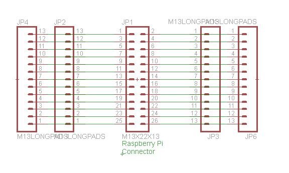
I did the project in eagle cad placing one Raspberry Pi 2×13 femal connector (step 2.54mm – 0,01″) and then placing 4 pin header strip 1×13 with enlarged pads.
I need these pads only for soldering the wires to the pcb.
 After this I did a very simple pcb putting in a simple layout all the components around the Raspberry connector.
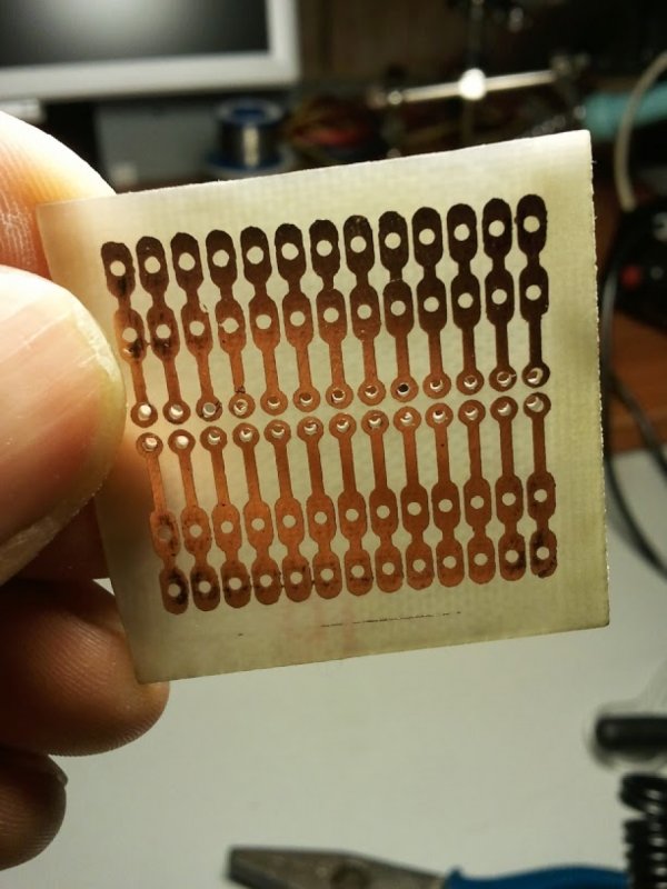
For the PCB realizaton I've used the common laser toner transfer system, etching the copper with a solution of HCl @15% + H2O2@36% vol.
If you want to use this sistem be careful with the acid exalations and make sure to do this in a open environement.
The Result
Whe I started playng with electronics I was very young (about fourtheen) and stopped my diy activities about in the year 2000 when I started working in the telco world.
 So this is my first attempt with a pcb in the “modern” age and I can consider the result as quite good.
Surely I've to work on the soldering side, but for this first attempt I'm satisfied.
Now It is time to play with this board in my several projects that I've in mind.
For more detail: DIY Raspberry Pi Connection Board Featured