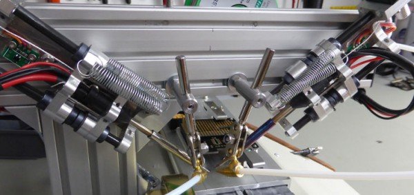
The DIY soldering robot which we have been building in our spare time over the past few months is now working and we have been able to solder some test Raspberry Pi expansion board headers with the machine.
Before starting on this robot we looked at the various commercial soldering systems that are available. Wave soldering machines would have been impractical as the connector is on the top side of the board next to the surface mount components. Wave soldering would also coat the full length of the pin in solder which we don’t want to do as it would make it more difficult to stack the boards.
There are several commercial soldering robots available and we got quotes for some of them but we decided that they were either too big, too slow or too expensive, with most costing more than a new car. In the end we decided that what we wanted was so specialized it would be easier and cheaper to make one ourselves.

The current speed of the machine is still very slow and the software was setup to allow us to run at a reduced rate so we could easily find any issues with alignment and solder feed. Once we have performed more test runs we will gradually increase the speed of the various stepper drives and feed systems until we can get good consistent soldering.
The previous blog posts detailed the various electronics and hardware stages and this post shows the final parts we had to build, modifications to the solder feeder systems, the software which drives the kflop controller, our custom control boards for the stepper driving and soldering irons elements heating control.
Previous blog posts:
- Antex TCS230 50W Temperature Controller
- Soldering Robot – Head Assembly
- Soldering Robot – Solder Feeder
- Soldering Robot – Temperature Controller
- Soldering Robot – Designing the Motor Driver Board
Case Build
We purchased a sloped instrument case from Farnell for this project as we wanted to be able to fit the Windows tablet computer to the front panel to run the machine. The case has wooden sides which would allow the signal from the Bluetooth module mounted on the control board to escape!
The flat bearings were mounted on 4mm aluminium and this was bolted to the top of the case and the rear vertical arm was fitted to the rear of the case using right-angle brackets to brace the metal against the rear of the case.
Once the bearings were fitted we found a problem with the bearing surfaces being difficult to keep in position due to the bearing material not being fixed to the mounting plates. We decided to replace the bearings with a moulded version which resolved the problems.
The power supply and the kflop controller board are bolted into the bottom of the case and the interface board, temperature controller and a 4 port usb hub are bolted onto the top of the case. The linear encoder sensor for the magnetic tape was also fitted into the top of the case and this connects to the interface board which is then connected to the kflop controller via a ribbon cable.
For more detail: DIY Soldering Robot – Project Completed

