
I live in an apartment complex with an individual carport that can only be accessed from the outside. This meant that I needed to carry the bulky garage remote every time I go out. Carrying this thing was a hassle. If I am not wearing a jacket, I really just have my pants pocket on both sides to store my phone, wallet, and keys. I don't really like using the back pocket for my wallet because sitting down becomes a hassle. And now I also needed to put this bulky remote control just to open my garage? Not only was it bulky, but it was sensitive, as well. There were times I accidentally clicked one of the buttons trying to get my phone out and then the garage door opened without me noticing. This was a real inconvenience, so I was thinking it would be nice if I can somehow open the garage from my phone.
At first, I thought about making a direct replacement controller that was smaller by figuring out the trigger frequency of the receiver that activates the garage door to open and close. But that would mean that I need to dig into the specs of this old device, and I didn't really want to spend too much time doing this. Plus, there was a good chance my device won't pair due to some security feature.
After some more thought, I decided to just make my own SwitchBot and mechanically press the existing remote control through my smartphone.
Supplies
Components:
- 2x Raspberry Pi 3 Model B or up
- 1x Arduino Uno
- 1x Adafruit Motorshield V1
- 1x 12V DC bi-directional motor with 6mm shaft
- 1x Boost converter
- 1x Raspberry Pi Camera Module
- 1x L-shaped sheet metal mount
- 1x 2.1mm barrel connector pair – female and male (you can also use 2.5mm barrel connector pair)
- 1x Smartphone
- 1x Wooden dowel pin
- 1x 6mm to 6mm rotatable coupling shaft
- 1x Acrylic sheet
- 2x 2.5A / 5V power supply
- 1x USB-B to USB-A cable
- 1x 24 gauge silicone wire spool – red
- 1x 24 gauge silicone wire spool – black
- 1x electrical tape
- 2x female-to-male breadboard jumper wires
Step 1:
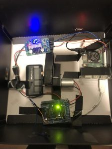
The Switchbot side:
This Raspberry Pi will constantly ping the server installed in the other Raspberry Pi with the camera for a numerical value of 0 or 1. The motor will activate and push the garage remote control if the value in the server is different from what it has stored.
Hardware:
- Mount the Adafruit Motorshield V1 (or V2) on top of an Arduino Uno.
- Connect the Arduino Uno to the Raspberry Pi with USB-B to USB-A cable.
- Note: USB-B side plugs into the Arduino Uno.
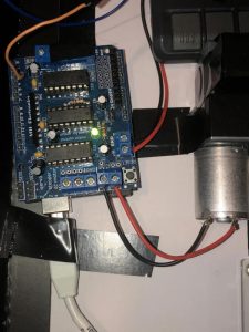
- Strip the ends of the 24 gauge wires and connect the motor to one of the DC motor side of the terminal blocks. Refer to the the picture.
- Note: You can find out more information on Adafruit Motorshield on https://learn.adafruit.com/adafruit-motor-shield
- Make sure the jumper on the Adafruit Motorshield is removed. It is best if you power the Arduino and the motorshield separately. Refer to the picture.
- Using 2 of the female-to-male breadboard jumper wires, connect one of the 5V I/O pin of Raspberry Pi to the IN plus side of the boost converter terminal block. Connect the other wire to the ground I/O pin to the IN minus side of the boost converter terminal block. Refer to the picture.
- Connect 2 24 gauge wires to the OUT side (plus and minus) of the boost converter terminal block to the 2.1mm barrel connector (jack or plug; it does not matter).
- Connect 2 24 gauge wires to the power terminal block of the motorshield and the other ends to the mating part of the 2.1mm barrel connector (if jack was used to connect the boost converter, use a plug or vice versa).
- Connect the barrel connectors together.
- Using a screw driver adjust the boost converter to output 12V. Since we are using a 12V motor, the motorshield must be powered by a 12V power supply.
- Insert the 6mm to 6mm rotatable coupling shaft on motor shaft and bend the coupling shaft 90 degrees.
- Insert the wooden dowel pin to the other side of the coupling shaft. This will be the rotating finger that presses the remote control.
- Plug in the power supply to the Raspberry Pi.
Software:
- Raspberry Pi Code (Python):
- Note: This Python script reads the server for value change and then feeds that value to the Arduino.
import requests
import serial
import time
import platform
import subprocess

# This is the USB port and baud rate of the Arduino Uno
ser = serial.Serial('/dev/ttyACM0', 9600)

url = "http://xxx.xxx.xxx.xxx:8090/door" # replace the x's with your own IP address of the rpi server
ping_ip = "<IP address>.local" # same as IP address of the rpi server

def ping(host):
    """
    Returns True if host (str) responds to a ping request.
    Remember that a host may not respond to a ping (ICMP) request even if the host name is valid.
    """

    # Option for the number of packets as a function of
    param = '-n' if platform.system().lower()=='windows' else '-c'

    # Building the command. Ex: "ping -c 1 google.com"
    command = ['ping', param, '1', host]

    return subprocess.call(command) == 0

while True:

    response = ping(ping_ip) # server is constantly pinged to make sure it is online
    #print(response)

    if(response):
        page = requests.get(url)
        status_raw = page.text
        status = status_raw[4:5]
        #print(status)

        if(status == '0'):
            ser.write(b'0')     # Feeding value of 0 to Arduino

        else:
            ser.write(b'1')     # Feeding value of 1 to Arduino

        time.sleep(1)

    else:
        print("No response from server.")
        time.sleep(5)
- Arduino Code:
- Note: This code reads the fed value from the Raspberry Pi and activates the motor.
#include <Wire.h>
#include <AFMotor.h>  //Make sure Adafruit Motorshield library is installed

AF_DCMotor motor(2, MOTOR12_64KHZ); // motor M2, 64KHz pwm

int r = 0;
int r_prev = 0;

void moveForward()
{
  motor.run(FORWARD);
}

void moveBackward()
{
  motor.run(BACKWARD);
}

void motorStop()
{
  motor.run(RELEASE);
}

void setup() {
  // put your setup code here, to run once:
  Serial.begin(9600);
  delay(10);

  motor.setSpeed(200); // 255 is max
}


void loop() {
  // put your main code here, to run repeatedly:
  if(Serial.available())
  {
    r = Serial.read() - '0';

    if(r != r_prev)
    {
      moveForward();
      delay(500);       //This rotates the motor forward for 500ms
      motorStop();
      delay(10);        //This gives a 10ms break before rotating in the opposite direction
      moveBackward();
      delay(440);       //This rotates the motore backward for 440ms
      motorStop();

      r_prev = r;       //This saves the last r value
    }

    else{
      motorStop();
    }
  }
}
Step 2:
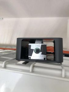
The Camera, Server, and Controller UI Side:
This Raspberry Pi is the camera, the server, and the controller. The smartphone will connect to remotely connect to this Raspberry Pi and gain access to the controller UI. When the button “Garage Door” is pressed, either a 0 or 1 is written to a text file, and then the server script running in the background reads this text file to upload it into the server. The value in the server is read by the other Raspberry Pi (Switchbot) to activate the motor.
Additionally, the controller UI activates the camera and can also record a video. The recorded file is saved into a folder called “recordings” located in /home/pi/Desktop. Just some extra features to make things more convenient.
Hardware:
- Connect the Raspberry Pi Camera Module to the Raspberry Pi (this is the other Raspberry Pi).
- Mount the camera to the L-shaped sheet metal mount to fix the camera (or any other method).
- Plug in the power supply to the Raspberry Pi.
Software:
- Controller UI Code (Python):
import tkinter
import tkinter.font as font
import subprocess, sys, os
import signal
import time
from datetime import datetime
from picamera import PiCamera

class Window(tkinter.Frame):

    def __init__(self, master=None):

        global pid     #pid of server

        tkinter.Frame.__init__(self, master)

        self.master = master

        self.init_window()

        # open/close garage door option
        self.garageDoor_boolean = False

        # record option
        self.record_boolean = False

        # start/stop camera option
        self.camera_boolean = False

        self.camera = PiCamera()

        # server start by activating a script called server.py
        self.args = ['python3','server.py', 'arg1', 'arg2']
        self.proc = subprocess.Popen(self.args, shell=False)
        pid = self.proc.pid
        print(pid)
        self.poll = self.proc.poll()

    def init_window(self):

        global button1
        global button2
        global button3

        self.master.title("Controller")

        self.pack(fill=tkinter.BOTH, expand=1)

        button1 = tkinter.Button(self, text="Start Recording", height = 5, width = 20, command=lambda: self.Record)
        button1.place(x=25, y=30)
        button1.bind('<ButtonRelease-1>', self.Record)

        button2 = tkinter.Button(self, text="Start Webcam", height = 5, width = 20, command=lambda: self.Webcam)
        button2.place(x=260, y=30)
        button2.bind('<ButtonRelease-1>', self.Webcam)

        button3 = tkinter.Button(self, text="Garage Door", height = 5, width = 20, command=lambda: self.Door)
        button3.place(x=150, y=200)
        button3.bind('<ButtonRelease-1>', self.Door)

    def Door(self, event=None):

        # write to text file door.txt
        if(self.garageDoor_boolean == False):
            with open('door.txt', 'w') as f:
                f.write('1')
            self.garageDoor_boolean = True
        else:
            with open('door.txt', 'w') as f:
                f.write('0')
            self.garageDoor_boolean = False

    def Record(self, event=None):

        self.camera.vflip = True
        self.camera.hflip = True

        if(self.record_boolean == False):
            timeStamp = datetime.now().strftime("%y%m%d_%H%M%S")
            self.camera.start_recording('/home/pi/Desktop/recordings/{}.h264'.format(timeStamp))
            self.record_boolean = True
            button1.config(text="Stop Recording")

        else:
            self.camera.stop_recording()
            self.record_boolean = False
            button1.config(text="Start Recording")

    def Webcam(self, event=None):

        # No need to apply below if your camera is already right-side up
        self.camera.vflip = True
        self.camera.hflip = True

        if(self.camera_boolean == False):
            self.camera.start_preview(fullscreen=False, window=(-10, 100, 640, 480))
            self.camera_boolean = True
            button2.config(text="Stop Webcam")

        else:
            self.camera.stop_preview()
            self.camera_boolean = False
            button2.config(text="Start Webcam")

def closeWindow():
    # terminate server
    print(pid)
    proc_terminate = os.kill(pid, signal.SIGTERM)
    # close window
    root.destroy()

root = tkinter.Tk()

h = 420 # height of tk window

# get screen width and height
ws = root.winfo_screenwidth() # width of the screen
hs = root.winfo_screenheight() # height of the screen

y = hs - h

root.geometry("480x400+0+%d" % (y))

app = Window(root)

root.protocol('WM_DELETE_WINDOW',closeWindow)

root.mainloop()
- Server Code (Python, Flask): server.py
from flask import Flask

app = Flask(__name__)

@app.route('/door')
def get_data():
    with open('door.txt', 'r') as f:    # Reading value from text file "door.txt"
        status_raw = f.readlines()
        status = str(status_raw)[2:3]
    return '<h5>{}</h5>'.format(status)

if __name__ == '__main__':
    app.run(host='0.0.0.0', port=8090, debug=True)
Step 3:
Finally, on the smartphone, download VNC Viewer from either the App Store (iOS) or Play Store (Android). Once downloaded, connect to the Raspberry Pi with the Controller UI and start playing around with it!
What's also nice is to have these Python scripts run automatically on boot up. Sparkfun explains how to do this very nicely. https://learn.sparkfun.com/tutorials/how-to-run-a-raspberry-pi-program-on-startup/all
Another thing I would like to mention is that a fan should be set up to keep the Raspberry Pis cool since they will always be on.