
These are instructions for building a computer-controlled tACS device.Transcranial alternating current stimulation (tACS) is a form of neuronal stimulation that operates by running an alternating current through the human brain. This current can be any waveform from random noise (tRNS is the official research term if you want to be fancy about it) to a clean sine wave. There is some evidence that the brain's own oscillation pattern will synchronize with externally applied alternating current(1), and specific cortical oscillation patterns may be associated with specific thought processes(2). Since EEGs directly record cortical oscillation patterns, it seems reasonable to hypothesize that these recorded patterns could be superimposed on a second brain using tACS in order to affect mental processing, and perhaps even to induce mental synchrony. The hardware described here is being developed for an experiment we're assembling to begin preliminary testing of this hypothesis. Humans who want to play with this hardware but don't want to build it shouldsign up for participation.
This is a backbone technology for the formation of the collective of superhuman cyborgs necessary to save the world. The development of this technology and others like it seems practically inevitable at this point. It is preferable that technologies such as this one, that could so profoundly influence humanity, be developed and implemented in an open manner — under the watchful guidance of the public at large — rather than secretly, by military or intelligence agencies.
Citations
(1) Transcranial alternating current stimulation (tACS), Walter Paulus et al., Frontiers in human neuroscience,http://www.ncbi.nlm.nih.gov/pmc/articles/PMC369536…
(2) Spectral fingerprints of large-scale neuronal interactions, Markus Siegel at al., Nature reviews neuroscience,http://www.nature.com/nrn/journal/v13/n2/full/nrn3…
Step 1: System Overview
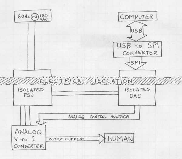
Since this device is to be attached to humans, safety is of utmost importance. For this reason, the electronics which are connected to the human are galvanically isolated from both the input power lines and the data input from the computer. In addition to electrical isolation, three redundant current limiting systems are used to ensure that the current through the human remains restricted to a safe level even in the event of multiple system failures.
As you can see from the block diagram above, the control signal for the device originates in a computer, which is connected to a USB to SPI converter. The converter sends an SPI signal to an isolated DAC, which converts the signal into an analog voltage. This analog voltage goes to a voltage to current converter, which supplies a regulated current to the human. The PSU powers all circuitry behind the isolation barrier. Let's look at each subsystem in more detail, from the human back.
Step 2: Voltage to current converter
The voltage to current converter has the dubious honor of being directly connected to the human. Extra care was taken in its design, as failure to appropriately limit the output current may cause undesired effects on the human (seizures, convulsions, immolation, death, et cetera). For this reason, most of the circuitry in the V to I converter is safety circuitry not strictly necessary for operation — this additional circuitry slightly degrades normal performance by decreasing the voltage headroom available for output and increasing output equivalent series resistance.
A block diagram has been provided in the hopes of clarifying the following, the principle of operation of the voltage to current converter: When the variable current source is set to 1mA, it only takes 1/3 of the current supplied by the 3mA source and the resulting current through the human is +2mA (3mA-1mA), and when the variable current source is set to 5mA, it takes 5/3 of the current supplied by the 3mA source and the resulting current through the human is -2mA (3mA-5mA). Sweeping the variable current source from 1mA to 5mA proportionally sweeps the current through the human from +2mA to -2mA. The active limiters never become activated during normal operation, and the passive limiter drops no more than 14V unless a fault occurs.
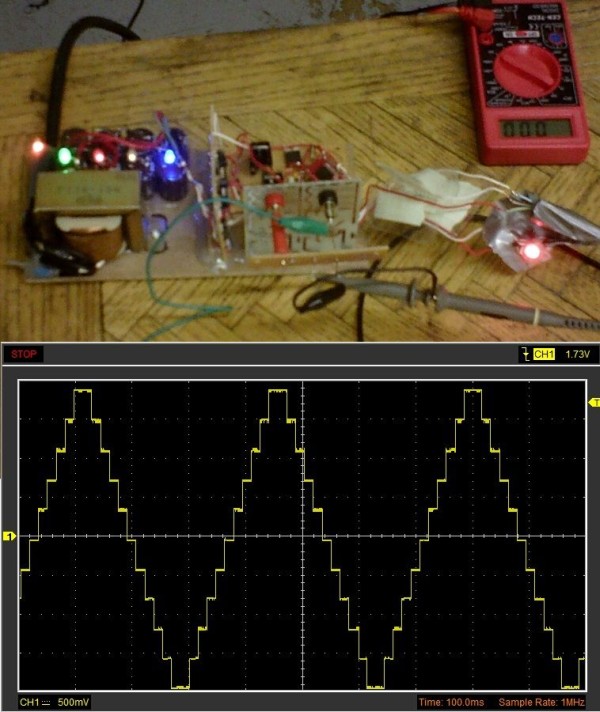
The second image is the actual schematic of the voltage to current converter. The functional blocks have dashed lines around them. If this schematic doesn't make sense to you by itself, I've put more detailed descriptions of each functional block in the next step. Attentive readers will find that the “1 – 5mA” current source is actually capable of going all the way down to zero. The actual current output of the voltage to current converter circuit is bounded as follows: DAC out = 0V, current = +2.9mA; DAC out = 5V, current = -2.4mA; with a linear relationship between DAC output and current between those points. Software must be used to limit the values sent to the DAC so that the output remains bounded within the +/-2mA limits prescribed by the Gottingen protocols (which were originally written for tDCS, yes, I know). The reason the positive current output capacity has that extra mA will be explained in the next step.
Step 3: Voltage to current converter subunits
Current limiting for normal operation is governed by simple one-transistor current regulators of the structure shown in the first two circuits. A voltage reference and a resistor are used to set the current, which will be roughly equal to (Vref – 0.65V) / R, as long as Vsupply has enough voltage to force the appropriate current through the load. This equation (approximately) applies for both NPN and PNP implementations, and is a rule of thumb only; it ignores base bias current and a whole bunch of other variables, but it should be accurate to within 5% most of the time. This type of current limiter begins to act in a nonlinear fashion if you allow the transistor to get too close to cut-off. (That's why the extra mA is in the positive supply fixed current source, so the negative supply variable current source never gets too close to cut-off.) The one-transistor current regulator works by maintaining a constant voltage across the resistor, thereby guaranteeing a constant current through the resistor.
The first backup layer of current limiting is provided by three-transistor discrete current limiters. These circuits are neat because they don't drop much voltage when they're not limiting current (under 2V), and they don't need any connections besides one input and one output. This circuit can only limit current flowing one direction, but you can use two of them in parallel (with one reversed) to limit alternating current if you want to. You can omit the diode if your application doesn't have a risk of current reversal. (The tACS shouldn't ever need this diode in its limiters, but I left them in for extra protection.) This three-transistor discrete current limiter limits the current to (0.65V) / (Rsense). The same “rule of thumb only” warning applies to this equation as the one in the paragraph above. Rbias needs to be small enough to saturate the darlington pair during normal operation, but large enough to allow only an insignificant percentage of the desired current limit through (through Rbias itself, that is). Here's how the limiter works: normally the darlington pair is saturated by current through Rbias (current flows freely). When the voltage across Rsense is big enough to turn on the transistor that's not in the darlington pair, that transistor begins turning off the darlington pair by removing its base current, keeping the voltage across Rsense limited to ~0.65V and thus limiting the current through Rsense, and through the circuit as a whole, assuming Rbias is big enough that the current through it can be ignored.
The bottom circuit in the second image is a subsection of the voltage-to-current converter sub-module, which contains an advanced current regulator sub-sub-module whose schematic is pictured here. This sub-sub-module limits current through it to (voltage across regulator) / (3*R). It utilizes three fixed-conductance sub-sub-sub-modules which were produced from hydrogen using the proton-proton chain fusion reaction process.
For more detail: DIY tACS: Hardware for machine-human telepathy experiments