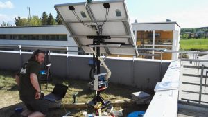
This project was one of my final projects I did on my exchange studies in Finland.
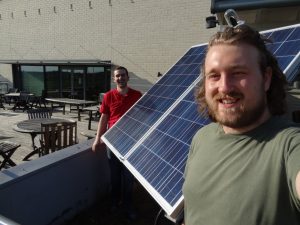
For this project I worked together with Fatbardh.
This is a much larger and more advanced version of one of my first projects ever.
Also a solar tracker: http://www.instructables.com/id/Arduino-Solar-Tracker/ .
The features of this solar tracker are:
- Solar tracking: making sure the solar panels are aligned to the sun as long as possible.
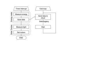
- Energy monitor: This measures the voltage and the current generated by the panels and calculates the generated Power and Energy.
- Data logging: this sends the data from the energy monitor into the cloud of ThingSpeak.
- Also there is an LCD to display the values of the energy monitor
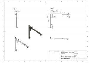
In this instructable are technical drawings of the project included. And at step 10 there is a link to the complete project report and presentation.
Why:
To read more about the energy profit from this kind of system please read this chapter on wikipedia.
This is also my entry for the 3D printing contest:
I would love to have a 3D printer. It will help me a lot to do other projects. To make gears and enclosures. So if you found this Instructable interesting please vote for my Instructable in the 3D printing contest.
My excuses for my spelling mistakes, you may always let me know if you see some.
Step 1: Overview
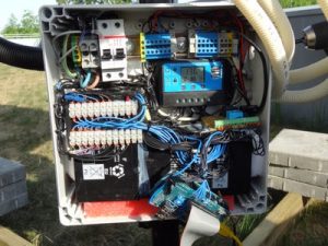
In this step I’ll go over all the used components in this project.
Solar panels:
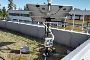
We used 2 solar panels of each 12V 150W which will bring the total to 300W.
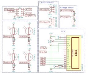
Energy Monitor:The energy monitor uses 2 current sensors, to measure the current.
And one voltage divider to get the voltage down to a voltage that the Arduino its analog-digital-converter or ADC can handle.
If you don't want to make it your self you can buy one as well: ebay link
Light direction sensor:
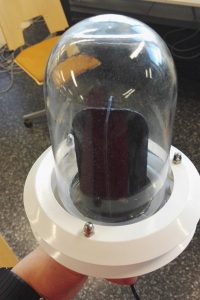
Light direction is detected by four Light dependent resistors or LDRs. Each of the LDRs is placed in a voltage divider and the signal is fed to the Arduino its ADC.
ebay link
The end stop Switch
The end stop makes sure the mechanical construction doesn’t collide in its self.
The motors
The motors are 12V linear actuators from internet.
And are controlled with a very simple H-bridge.
ESP8266
The ESP8266 is a cheap WIFI module which we use to send the data to a ThingSpeak datastream
The LCD
The display is used to display the energy monitor values
The microcontroller
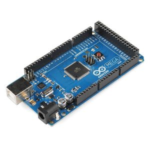
The microcontroller we used was an Arduino ATMEGA 2560
Arduino MEGA 2560 R3 ~10$ – Ebay
The charger
For the charger you should search for a MPPT (max power point tracking) chager. And for sure not buy the one in the picture because this one overcharged our batteries and is not MPPT.
Step 2: Mechanical Construction.
We both didn't had a lot of experience with metal working. Because of this we got help from a local vocational school.
The construction exists of a strong steel beam, in which a second part is placed, by sliding in a rod in a hole. To this set-up are levers added to which we connect the linear actuators.
Have a look at the technical drawings (PDF) and the pictures to get a better idea of what it looks like.
The technical drawings and the renderings are made with Fusion 360
Step 3: The Light Sensor
This is the same principle as the previous version. 4 LDRs separated by a crossbeam. This time the crossbeam was 3d printed.
It works by comparing the average of LDR values of each side to determine which side to rotate to.
LDR holder 3d model: http://www.thingiverse.com/thing:1500571
Step 4: Motor Control Algorithm
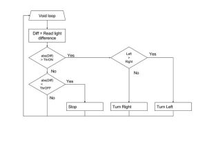
The motor control algorithm is responsible for turning the motors on and off. This all depending on the data of the ligh sensor.
This also improved compared to my previous version. Now there is a hysteresis implemented. Comparable to a Schmitt trigger. So the motor turns only in if the light difference is larger than a certain threshold value, and it will only stop if the light difference is below a certain value.
Step 5: Energy Monitoring
The energy monitor works by measuring the voltage and current output of the panels.
By multiplying these two values you get the generated power.
P = U * I
P= Power in Watt; U = Voltage in Volt; I = Current in Ampere.
By integrating the Power over time you'll get the total generated Power.
Voltage measurement
The voltage measurement is done by a voltage divider over the panels output. To get the output range of the panels 0-22V down to a range of 0-5V to protect the analog-digital-converter.
Current measurement
The current measurement is done by two ACS712 hall effect current sensors.
Step 6: Data Logging
The data logging is done by sending all the data to a ThingSpeak channel.
This is done by an ESP8266 WIFI module.
Step 7: Microcontroller
You can get an Arduino MEGA 2560 clone on ebay for somewhere in-between 5$-15$
Step 8: Software
If you want to use this code you should have a look at:
- EnergyMonConnections.h
- connections for the energy measurement
- solartrackerdefines.h
- settings and conenctions for the LDRs and solar tracker
- solarPanel.h
- to set the formulas right for the calculations of the ADC
- internet.h
- set wifi name and password aswell as api key
Step 9: Final Results!
Step 10: More Information
For much more information about this project.
I would like to recommend you my project report and presentation.
Step 11: Questions
If you have any questions, feel free to ask. If you can't find your answer in the comment section.
And I'll try to add more information to the Instructable depending where the most questions are about.
I hope you had fun reading my Instructable.


