
Step: 8) Find reusable modules from the circuit diagram
Whenever we do hardware designing, the first rule is to make it in modules that can be reusable. The modules that we make for this particular project may come useful in another project and hence reduce the development time for that project. Even if a module is in use and at the same time found to be useful in another project, we can build another copy of the same module keeping the circuit design and PCB design same. In short this method can save a lot of time and hard work in the development process.
 The module marked [A] can be called the IR RECEIVER module. Its purpose is to receive the IR rays and produce an output according to their intensity. This module can be used in other IR based projects. The module marked [B] can be called as the COMPARATOR module and can be used for the comparison process in other projects. This module has an output and inverted output. The module marked [C] is called the MONOSTABLE module.
This module has two mono stables which can be operated separately. Even though there were two separate mono stable block in the block diagram we have selected this as a one single module due to the fact that a single LM358 IC is used to realize both the blocks. If we make it two different blocks we have to use two LM358 ICs with one of the comparator not used. The module marked [D] is called the RELAY module and it consist of three individually accessible relays. The module [E] is called the indicator module and can be used with indication purpose in all other circuits. The module marked [F] is called the regulator module and is obviously useful in all circuits.
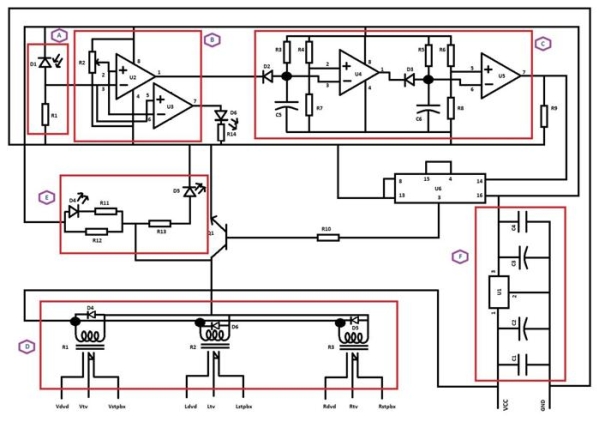 We haven’t made the piece of circuit representing the BISTABLE block into a module since we can realize the bi stable module with much simpler circuit than using a CD4017 which is basically a counter. Also there is no point is making the IR INDICATOR circuit with only an LED and a resistor into a separate module.
We have selected the modules from the circuit not at all based on the block diagram of the project, but based on the reusability and the efficient utilization of the available components.
For mroe detail: Electronic Circuit Designing Multitasking with Circuits (Part 4)