
1. BACKGROUND
1.1. Related Work
In 2015, Harvard designed an assisted motion glove to give grip strength and lifting support to
humans with hand impairments. [1]
The soft glove design is made to be wearable and lightweight
for the user. The glove would detect weak EMG specific signal locations to move the gears on
the robot in a specific way to model a real human grip. sEMG sensors were implemented to
better suit each individual user.
An EMG Human-Machine interface system was designed by researchers to control a robot by
reading and analyzing EMG signals produced by eye movement. Feature detections where
applied by analyzing the voltage threshold of the signal. The EMG system implemented a path
planning algorithm which classifies certain eye movements with approximately a 95.71%
accuracy. This system was able to use eye movements to move the robot platform.
Most biomedical field applications obtain and read these signals through the use of placing
surface adhesive pads on the skin of the patient. The alternative to this method, is reading the
signals intravenously by the injecting a needle into the muscle of the body to read these signals
directly. These applications can benefit those with muscle and nerve damage.
1.2 EMG Signals
Electromyogram (EMG) signals are electric potential generated by muscle cells after being
activated by the nervous system. The more force we apply to the muscle the greater the action
potential, generating a larger electric potential from the muscle cells. In theory, anywhere from
10 Hz to 500 Hz is the typical range of any EMG signal that will be produced by the human
body. A raw EMG signal will have a range of -5 to +5 mV before amplification. This value may
seem small in nature, but after amplification of the signal can produce very valuable data to
researchers.
In most medical and engineering applications, the detection of these signals will be done through
surface EMG sensors. They are called surface EMG signals because the material that will be
used to detect these signals are placed by an adhesive electrode on the surface of the skin. They
obtain useful data on the time and intensity of muscle activation with advantages of being quick
and noninvasive to apply. Disadvantages to using a surface emg sensor is the amount of error
accumulated from skin, fat, and cross-talk between muscles. The use of medical equipment and
human machine interface have been revolutionized by EMG signals, allowing researchers even
further understanding of the human body. Even though these signals are hard to classify due to
the almost random nature of the action potential, patterns or probability classification can be
implemented to classify the signals. Most medical field applications are called Myoelectric
control systems and are predominately used with upper-limb prostheses and electric-powered
wheelchairs.
1.3 Neural Networks
Artificial Neural Networks are a computational model that is based off human brain thought
process. Neural Networks utilize artificial neurons that link with many other neurons to activate
or inhibit the specific output neurons of a system. This system is closely related to a simplified
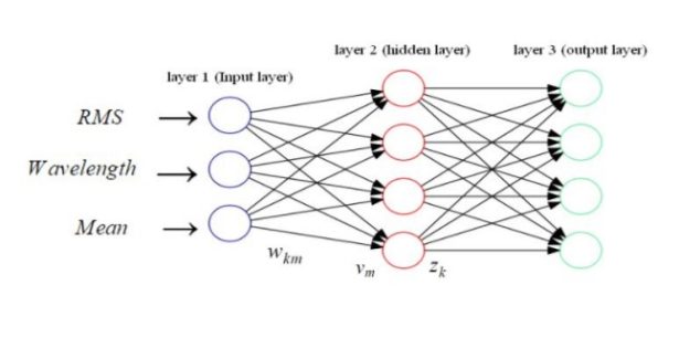
version of how the human brain’s axons and synapses work together. An example of an single
neuron artificial network diagram is shown in Figure 1.
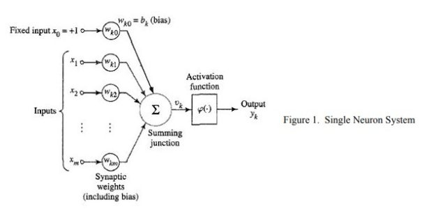
Most artificial neural networks include multiple layers consisting of one input layer, single or
multiple hidden layers, and one output layer. The input layer consists of the data inputs into the
neural network. The hidden layers contain a summation function that takes into account the past
layer’s output and the weight for the new layer. This is shown in figure 1 as summation (1) over
all inputs of (Xm) multiplied by the weights ( W ) corresponding to the respective input. These km
weights and bias are typically found through system learning using training sets of data, which
the desired output is already known. When the optimal weights and bias are determined, the
neuron pre-activated outputs are processed through an activation function to determine the
activated output.
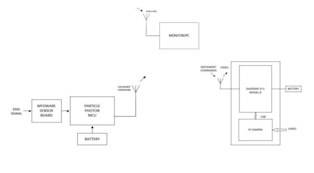
PROJECT DESCRIPTION
The system includes an EMG control, wheeled service robot and monitor subsystems. A
MyoWare muscle sensor board was used to read EMG signals from the user that were then
transmitted to the Particle Photon’s analog to digital converter for advanced signal processing.
The Photon then calibrated the system for the user which classified four different commands
through the implementation of an artificial neural network (ANN). Upon completion of the
classification and calibration of signals the user was then able to send one of four commands to
move the robot through WiFi. The four hand and finger commands that the user had to calibrate
were for forward, stop, left and right motor control commands.
The wheeled service robot would receive one of four commands through a TCP/IP protocol that
was established by the Particle. The Raspberry Pi would then read the command and generate
specific pulse width modulation (PWM) signals. Simultaneously, while the Raspberry Pi moved
the robot, it also established a web server that displayed the four commands that the user used
along with a live video feedback of the robot’s path on a computer monitor.
3. SYSTEM DESIGN AND IMPLEMENTATION
3.1 EMG Control Subsystem
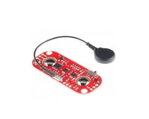
The EMG control subsystem utilized a MyoWare muscle sensor board and Particle Photon
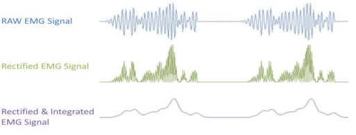
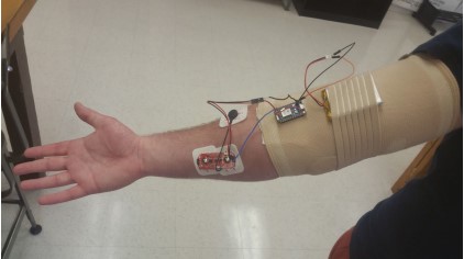
microcontroller for signal analysis, classification, and communication. The MyoWare muscle
sensor board shown in Figure 4 used electrodes placed over the skin on the brachioradialis
muscle to detect electric potential of muscle contractions. The sensor board amplified, rectified,
and integrated the signal to provide a clean signal for the particle photon’s analog-to-digital
converter. Figure 4 shows the how the MyoWare muscle sensor board processed the signal for
the analog to digital converter.
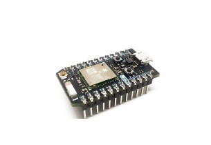
The particle photon shown in Figure 5 then converted the signal using a analog to digital
conversion with 12 bit resolution and a sampling rate of 10,000 Hz. The photon providing a
reference 3.3v translated a .8mV per level conversion. Allowing for a translation of analog signal
to the corresponding digital number between 0 and 4095. The photon then used event detection
to begin sampling of the MyoWare board’s incoming data. The voltage threshold to begin
sampling was set at 400 levels or the corresponding voltage of 320 mV. The voltage threshold
was used to filter out random movement noise and provide a more accurate segment extraction.
A maximum sample threshold set at 5000 samples or the corresponding to 500 ms was used to
limit the length of a segment and provide accurate movement segments. A minimum sample
threshold of 1000 was used to also filter out unwanted random signals. Thresholds were
determined experimentally through measurements of the signals on an oscilloscope. Based on the
thresholds, once sampling began the equations shown below were updated with new values.
Features were extracted from the segments using the continuous updating were root mean
squared (2), wavelength (3) and mean signal value (4).
Once the features were extracted from the segments depending on the current system mode,
calibration or operational, the segment was passed to a artificial neural network to be used in
network learning or motion classification. In calibration mode the current operator of the system
is asked to repeat a specific motion five times, saving the extracted features to be used in the
ANN, shown in Figure 7.
The artificial neural network was a 3 layer feedforward network consisting of 3 inputs, 4 hidden
nodes, and 4 outputs shown in Figure 7. For this project, the sigmoid activation function (5) was
chosen for the hidden layer, because the sigmoid function is ideal for implementing with
multiple layer neural networks and allows for small changes in the output when there are small
changes in the error allowing for smooth learning.
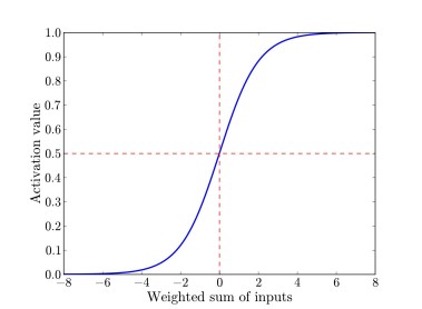
Graph displaying sigmoid activation
function squashing the pre-activation
output to a value between 0 and 1.
Instead of a sigmoid activation function,
the output layer used a softmax function
(6) output function. This is because the output layer consisted of multiple output neurons, and
softmax allowed the ANN to output a categorical distribution of all the output neurons. This is
important for the system, because it allows for ease of determining the correct output
classification.
Using the softmax function in output layer allows our network to learn by minimizing the cost
function (7) of the neural network.
Equation 7 describes the cross entropy cost function, where y is the desired output and z is the
actual output. The cost function is essential to the system to allow for incremental changes in the
weights and bias to produce the optimal numbers. To minimize the cost function, or to learn, the
neural network implements back propagation with gradient descent to find the errors within each
layer. Backpropagation is the computation of error, the gradient, backward through the system.
Error of the output was computed by using equation 8, which is the difference between the
desired output and the actual output.
Using the output layer error, the hidden layer error is then computed by using equation 9. The
layers’ errors were then used in the gradient descent to find the new weights and biases.
A graphical representation of gradient descent is shown in figure 9, displaying how the weight
and bias will decrease until reaching a global cost function minimum. Utilizing the equations 10 and 11, we
calculate the new layer's weights and biases respectively based on this theory.
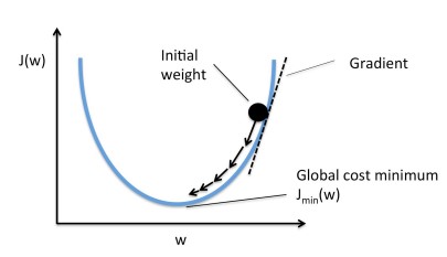
Graphical Representation
Once the gradient descent has reached the global cost minimum the system will stop learning and
the system will enter operational mode. In operational mode, the neural network classifier
determined the motion classification using the weights and biases produced during calibration.
The classified output from the neural network is a movement command which was transmitted to
the Raspberry Pi using TCP/IP IEEE 802.11 protocol.
3.2 Wheeled Service Robot and Monitor Subsystem
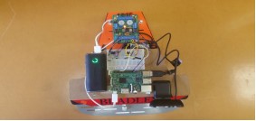
The wheeled service robot is powered by 12V center tapped battery and equipped with dual
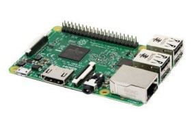
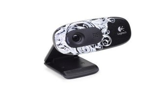
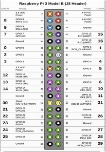
differential drive motors. External hardware implemented on the robot was a Raspberry Pi 3
Model B along with a Logitech C260 webcam. The Raspberry Pi was powered by 5 V USB
power bank to ensure the free movement of the robot without having to be plugged into a wall
socket for power. The operating system (OS) Raspbian Jessie Lite was chosen due to open
source access and its command line features along with extensive previous experience with it.
The specific version of Raspbian Jessie Lite was distributed on 11-17-2016. The lite version was
installed because the GUI was not necessary since the Raspberry Pi would be headless once it
was fully implemented on the robot. Headless for the Raspberry Pi means physically independent
of other subsystems and runs the specified programs without user interaction. Once the SD card
with the OS was mounted, a GPIO interface library, WiringPi, was installed in order to use the
GPIO pins for PWM signal generation. The Raspberry Pi 3 has two PWM channels, four
physical pins, on its forty GPIO header that may be used. Physical pins 12 and 33 were used on
PWM channel zero and one respectively. Two different channels were used to ensure that the
two pins generated different PWM signals allowing the robot’s left and right turns. If one
channel is used both pins would have produced the same PWM signal not allowing the robot to
produce a left or right turn. The code to implement this configuration can be found in Appendix
A.
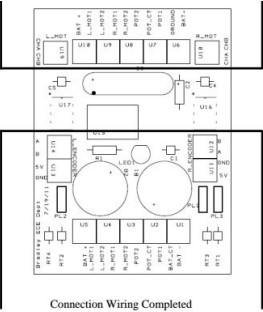
The motor control circuit implemented was a power transistor circuit to ensure that the PWM
signals would have enough current to turn on the motors. The transistor circuit acts as a gate,
which is a amplifier circuit, to allow voltage to pass through corresponding motor control pin
generated by the Raspberry Pi. The circuit consisted of two TIP 31A power transistors, two 1k
resistors for current limiting and two transistor base to ground 100k resistors used to guarantee
the transistor turns off completely. Two diodes were added in parallel of each motor to protect
from inverted voltage polarity.
Each PWM signal was fed through the base of the transistor to turn on or off the transistor
allowing the 6 V robot battery to power the motor control pins L_MOT1 and R_MOT1. This
configuration can be seen in Figure 13 and 14.
As stated earlier a TCP/IP IEEE 802.11 protocol was used for communication between both
subsystems. The Raspberry Pi runs the server.c file, found in Appendix B, then waits to receive
one of four commands to move the robot. Upon receiving a command the Raspberry Pi generated
the specified PWM signals to the two hardware PWM pins. For example if the received
command for the robot is to turn left, R_MOT1 pin’s input will generate a PWM signal while
L_MOT1 would remain shut off. The duty cycle of each command, besides the stop command,
had a 97% duty cycle. A 100 % duty cycle can be implemented by setting the PWM count in the
wiringPi specific function to 1024.
Simultaneously the Raspberry Pi would feed the video to a self-hosted website server. The
website was implemented by the use of a Trivial Network Protocol (TNP) to ensure that the
correct HTML code would be generated. The video monitoring subsystem was designed so the
user had a live video feedback of where the robot was located in their home and always have
access to user instructions and commands. The USB camera was attached to the Raspberry Pi
that fed the video through Motion, an open source library, to generate a live video feed on the
Raspberry Pi’s network IP address. Motion’s configuration file was set to have a resolution of
680 x 480, 30 frames per second (FPS) which is standard for a video to have little latency.
This video was embedded into a website to display the live video for navigation and instructions
for the user on their home monitor. The user’s personal website was accessed by searching the
url http://‘pi_address’.com which the Raspberry Pi generates upon booting up. The video
feedback was designed so the user had private live video feed under their own network.
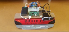
3.3 Stinger Robot
The Stinger Robot was used for system validation. The purpose of the robot was to verify PWM
signal generation, communication between all subsystems and the hosting of a web server.
Another reason why the this particular robot was chosen was because of previous experience
with this particular platform and provided in house by Bradley University Electrical and
Computer Engineering department.
4. RESULTS
The variation of voltages within the movements are based on where the sensor board is placed on
the forearm muscle. The targeted muscles of the sensor board were the brachioradialis and flexor
carpi radialis. It was crucial to place the board in this configuration in order to ensure that each
finger and hand movement can generate a feasible voltage signal. This configuration was
successful, because the system generated four different unique voltage signals above the sample
threshold to be used for the ANN.
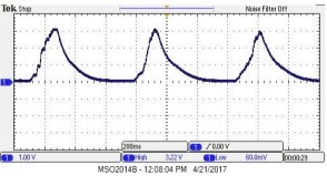
4.1 Test Subject 1
The four oscilloscope readings represent each of the four commands the user will implement,
shown in Figures 17-20. The muscle sensor board was capable of uniquely read and analyze
different finger and hand movements. Figure 14 presents the flexion of the wrist which the user
did three consecutive times and had a peak voltage of 3.22 V. In figure 14 the user made a fist
three times and produced a peak voltage of 2.10 V. The user then exerted his ring finger three
times which produced a peak voltage of 2.38 V. Finally the user exerted his middle finger three
times with the peak voltage being 1.5 V.
4.2 Test Subject 2
Subject two also did the exact four commands and are displayed in figures 17 through 20. Figure
17 presents the flexion of the wrist which the user did three consecutive times and had a peak
voltage of 2.66 V. In figure 18 the user made a fist three times and produced a peak voltage of
2.82 V. In figure 19 the user then exerted his ring finger three times which produced a peak
voltage of 1.70 V. Finally the user exerted his middle finger three times with the peak voltage
being 2.5 V in figure 20. Subject two had substantially different readings then subject one
because of a natural tremor they have. The system was still able to classify and categorizes these
signals to move the robot.
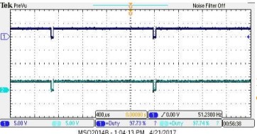
4.3 PWM Output
The duty cycle of all generated PWM signals were set at 97% duty cycle. Each motor pin
terminal had a oscilloscope channel attached to verify the duty cycle set GPIO pins of the
Raspberry Pi 3.
When the motor goes forward both pins should be able to generate a PWM signal. Also both pins should
simultaneously generate PWM with little latency at the exact same time to ensure that the robot would
move forward. This was verified as both pins had a duty cycle of 97% and turned the motor on at same
time. Figure 20 represents both pins on meaning the robot is in a straight path.
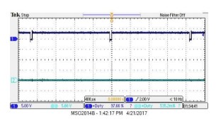
Command
When a turn command is given only one GPIO pin should generate a PWM signal. The other
GPIO pin would be set low so the motor one not turn on for that respective turn. Figure 22
represents left turn. In order for the robot to turn left the right motor would turn on while the left
motor is off. Figure 23 is the opposite and it shows that the other pin is now off and the other pin
is set to high to a 97% duty cycle. This configuration is for a right turn.
4.4 Website
The Raspberry Pi 3 was able to host the website for robot navigation and user instructions.
Figure 26 is the website that the user of this system will be able to locate on the IP address that is
assigned to the Raspberry Pi 3.

5. DISCUSSION
This project proposed a wearable EMG-based human machine interface system for in home
assistance. The system consisted of three main subsystems, EMG control, robot service, and
video monitoring subsystem. The EMG control was successfully implemented on the Particle
Photon, and has achieved partial accuracy with the artificial neural network classification system.
Considering the results, the number of sensors used to detect the EMG signals were found to be
the limiting factor in this classification system.
The only consideration that was taken into account for the robot subsystem was that the
Raspberry Pi generate PWM signals to move the wheeled robot. A larger platform would be
needed for “real” applications.
6. CONCLUSION
Upon completion a wearable EMG human machine interface system has been developed. The
system has successfully acquired EMG signals and extracted from the MyoWare muscle sensor
board. The system can calibrate and classify EMG signals from different movements performed
by the user of the system. The communication system was successful in transmitting commands
from EMG control subsystem to be received accurately by the service robot system. A web
server was implemented to provide live video feedback and instructions to the user.
7. FUTURE WORK
Future work in this project for the EMG control subsystem would include expanding to a larger
mcu control board for a greater capacity of EMG sensors for a better accuracy of motion
classifications. Other possible changes for better accuracy can include various other
classification techniques, including probability classification, or investigation into other possible
segment features including wavelet transform. If a proper amplifier chip can be implemented to
reduce noise then the raw signal of the EMG may be used for signal analysis, which may
improve accuracy of the classification.
The Pioneer P3-DX can replace the current robot to demo in a non-stationary environment, or
robot with a servo motors can solve dual differential drive issue. There are many python gpio
libraries to implement the code algorithm for the servo motors. The reason why the current robot
can not drive straight with dual differential drive motor and caster ball wheel move separately
based on separate PWM signals. In order to fix this problem some sort of feedback will have to
be implemented so the robot can self correct. A more compatible usb can fix the issue regarding
the timeout of the live feed. In the Motion documentation they have a table of all other
compatible usb cameras that has been tested by others. A proper lithium battery is better suited
for the wearable subsystem along with Pi being powered on by a higher current output around
2A.