
ESP12e oled “smartwatch”, honestly it's a wrist display 😉
The goal
Make use of ESP12e, do something smartwatch-like.
Usability
Fun mostly
Code
Hardware
Description
Recently I bought two ESP12e, wanted to see how those IoT things work. One thing I know for sure, they don't tolerate 12V 1A 😉 yep fired one by accident …
I left with one working, trying to figure out what should I build with it. In the meantime was wondering should I by a smartwatch, do I really need one? What would I use it for etc… then start googling about it, check some stores at net, overall research. At the end I thought, I don't really need one, but wait … maybe I'll build my own “smartwatch”, took ESP12e out from my drawer.
I does not have any fancy features like mp3 player, accelerometer, gps .., it's an oled display connected to ESP12e with charging circuit and FT232R for PC communication. It has two buttons, one bright red led connected to ESP12e used for urgent notify, also two for TP4056 charger circuit (red and green).
Esp12e is configured as an access point with WPA2.
Current software functionality
ESP12e is flashed with nodeMCU precompilled image (changed uart speed to 115200), also 107 byte of esp_init_data_default.bin was changed, so I could get ADC value from ADC pin, not from Vin.
Device has two buttons on the bottom (left/right).
Button on the right is connected to GPIO0, so when hold during boot it will enter boot mode and new firmware (e.g. nodeMCU) could be flashed.
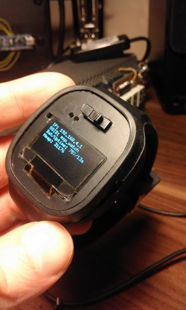
Left button switch display into two modes: status screen (picture above) and user screen.
Status screen has:
– ip address of the access point
– ssid of AP network
– battery pack level in ADC value: (620 dead, 760 fully charged) / uptime in seconds
– heap usage
– ip of connected wireless client
– mac address of connected wireless client
IP and mac of connected client is missing on picture above, because AP was idle that time.
After connecting to the ESP12e, we're getting IP as usual, and we can connect to port 80 of ESP12e. From now we can run any command on the nodeMCU, thanks to node.input(“command”) method. Result could be seen on serial port.
I thought about some low-level logic here, to send packed struct, unpack and display, but node.intput() is the simplest way to do this and very universal from other point of view e.g. I could change/put new files onto the 4MB ESP12e flash by wifi!
User screen:
– line 0
– line 1
– line 2
– line 3
– line 4
– line 5
All lines are described as l0..5 global variable defined in one of the files loaded to nodeMCU. So when want to update e.g line 3, we should do something like this:
|
1
|
echo 'l3="Hey is it working?"' | nc 192.168.4.1 80 |
Basically we assign value to global “l3” variable and we do this by nodeMCU eLua interpreter.
If we want to run urgent user notify function (bright led blinking), we just do:
|
1
|
echo 'notify_on()' | nc 192.168.4.1 80 |
btw. notification is switched off by pressing right side button.
Thanks to nodeMCU this is quite easy 🙂
We can pass also whole file with code or commands e.g.
|
1
2
3
4
|
bash> cat example.txtl0=" line0"l2=" line2"l5=" line5" |
|
1
|
cat example.txt | nc 192.168.4.1 80 |
I just finished this day ago, so don't be worried it will have more features, current software version was made mostly for testing.
Device can run about 4 hours at internal 400mAh battery pack, with image loop timed to 1 second and receiving data every second too. I've not used node.dsleep() mode here, because want to find out how long it will be working on raw eLua scripts, so power consumptions improvements are possible in the future 🙂 The wireless client was near to the device, I wonder how power consumption will jump, when be far away from it.
Overall info
Charger circuit is based on TP4056. This chip has two output on which you can connect leds or something else. Originally I've connected GPIO2 to “charging low output”, but that was a mistake, because ESP12e won't boot when you manipulate with GPIO2 during power on. So I cut the connection between TP4056 and ESP12e and add additional red led that you can see below. Sad that GPIO2 is left unconnected, for the next time I'll choose it as a button, just like GPIO0.
Main idea was, that ESP12e will be notified by 4056 that charging is in progress or is ended. In theory I could swap GPIO2 with already working left side button, but the routes was under the ESP12e so I leave it like this.
On the right side there is micro usb socket, used for charging, and also for nodeMCU console and flash loading. There is a FT232R inside, so after connect to PC it's seen as a serial port.
I was amused that this micro usb socket is so stable, it was looking so weak during soldering.
When I decided to make it, I've searched something for a watch envelope on the net. I found something that is nearly perfect. This is a strip from Jelly Watch, they come out with different colors, so If your girlfriend like that kind of gadgets, you can buy her white, yellow or pink one 😉 As you can probably guess it's all made from rubber.
Oh man, I was cutting this plastic front with a scalpel, mini-driller, metal file and good know what else for 2 hours.
For More Details: ESP12e + OLED display – a try to make a smartwatch