Overview
Being a bit of an unecessary geek, I’ve decided to pimp out my fishtank with a Feeding Time button!
“What’s one of those?” I hear you ask! Well… As it’s a Marine Reef tank, it’s a bit fiddly to feed some of the corals directly with the powerheads (underwater fans) running, so it’s often useful to turn things off that agitate the water.
I considered having hardwired relays going to each plugsocket that I wanted to control, but aside from the advantages (ability to verify state, confirming that a socket is on/off etc), I didn’t fancy playing around with Mains voltages- especially on something that’s so close to large amounts of water!
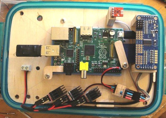
So, instead I opted to grab some Remote Control plug sockets, and control these with a Raspberry Pi (which I happened to have underneath the tank already… See: Aquarium Moonlight Controller)
The Sockets
There’s a few different types of Remote Control sockets, but the ones I opted for look like this:
IMAGE_HERE
I grabbed these from Amazon, but I’ve seen them on Ebay and a few other places too- I bought one pack of three, plus an additional standalone plug- which also means I have two remote controls too; not that I need them
[important]You can use pretty much ANY remote control sockets that have a Remote Control, but you will likely need to *manually* update the Remote Codes in the “switch” script! This involves a fair bit of technical faffing-about, but is well documented here: Hoagies House – RC Sockets
You can also find the original source code for the “switch” script here too![/important]
Design
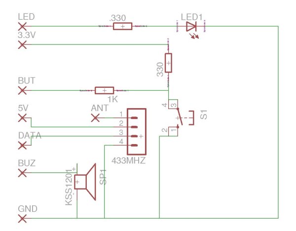
Now I had my plugs, I needed a transmitter. I went for this 433Mhz Transmitter LINK_HERE – but you should find that any similarly cheap 433MHz transmitter should work fine- just ensure you redesign the PCB and/or connect up the pins correctly as the pin layout may change between transmitters!
For the design, I wanted:
- An LED to signify when FishFeedTime was active
- A buzzer to signify “Start”, “Warning”, and “Stop” statuses.
- 433Mhz Transmitter to control the Sockets
- A Push Button to Start/Stop FishFeedTime.
I set out to prototype the kit on a breadboard, before drawing up a PCB to be fabricated by
Code
To deploy the code, we assume you have SSH access to your Raspberry Pi (check the Raspberry Pi help pages if you’re unsure on this.)
- SSH to your Pi, as a User with “sudo” access!
- Get the code:
|
1
2
3
4
5
6
7
8
|
# Install gitsudo apt-get update && sudo apt-get install git# Download the code:git clone https://github.com/dalgibbard/fishfeedtime# Go into the newly made directory:cd fishfeedtime |

|
1
2
3
4
5
|
# Kind unnecessary... as the script runs as root, but# I ended up adding sudoers perms to this user so it can control the init script## Importantly though, if you change any of this, you'll need to change the init script too <img src="//dgunix.com/wp-includes/images/smilies/simple-smile.png" alt=":)" class="wp-smiley" style="height: 1em; max-height: 1em;">sudo useradd -m -s/bin/bash fishfeedtime |
- Deploy main and init scripts
|
1
2
3
4
5
6
7
|
sudo mkdir ~fishfeedtime/fishfeedtimesudo mv fishfeedtime.py switch ~fishfeedtime/fishfeedtime/sudo mv fishfeedtime_init /etc/init.d/fishfeedtimesudo chmod a+x ~fishfeedtime/fishfeedtime/fishfeedtime.pysudo chmod a+x /etc/init.d/fishfeedtimesudo update-rc.d fishfeedtime defaultssudo update-rc.d fishfeedtime enable |
- Configure Your Sockets
For this part- run the configuration script FIRST!:
|
1
|
sudo configure_sockets.sh |
This will configure each channel, one-by-one.
If you don’t care about being able to control the sockets individually in some other code (which I do!), then you can just stick them all onto Channel 1 if thats easier
For more detail: Fish Feed Time – Wireless Socket Control with the Raspberry Pi


