
Introduction
The success of the ESP8266 from Espressif Systems is undeniable. It is a powerful microcontroller with built-in Wi-Fi capabilities and is readily adaptable to a multitude of uses in the rapidly growing IoT (Internet of Things). One of the few difficulties to using the IC has been updating the firmware in the thousands and thousands of development modules that have permeated the market. Judging by the large number of comments posted, this article on All About Circuits has been a help to many. However, the passage of time has revealed some corrections and improvements needed in the information that was provided in October of 2015, and presenting that information is the goal of this article.
Specifically, the following improvements will be addressed:
- a better flashing circuit
- an easier-to-use terminal program
- a revised Flash Download Tool
- updated SDK v2.0.0 ESP8266 firmware
Taken collectively, and supported by better documentation from Espressif, these changes will streamline the firmware flashing process, and increase the ESP8266's usability to both hobbyists and professional designers.
As a note, this article is a successor to a previous version that was published in October of 2015. You may want to peruse that article for some worthwhile background information.
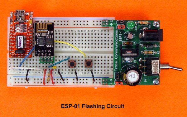
The Flashing Circuit
An improved flashing circuit for the ESP-01 module is shown in the following schematic diagram; several changes have been made to the original design:
- The 3.3VDC power is no longer taken from the USB-to-TTL converter. Some converters do not provide sufficient current to properly drive the ESP8266, especially when it is in the Wi-Fi transmitting mode. A separate, well-filtered and regulated 3.3VDC supply capable of supplying at least 500mA should be used.
- Capacitors C1 and C2 have been added to provide noise reduction on the power bus. They should be located as close as possible to the Gnd and Vcc pins on the ESP8266.
- R2 and R3 are pullup resistors that were added to ensure that the GPIO2 and GPIO0 pins on the ESP8266 are never allowed to float.
These changes do not indicate that the original flashing circuit was nonfunctional; the fact is that it did work for the author and for many other users. However, its shortcomings were such that the circuit could and did fail for some users at least some of the time. These failures could have been due to differences in environmental factors, power supply quality, and/or component tolerances. The improved circuit should eliminate those weaknesses.
Read More: How to Flash ESP-01 Firmware to the KImproved SD v2.0.0