
Introduction
The Raspberry Pi is a powerful platform to build a variety of projects on. Its full Linux operating system and large variety of peripherals make it extremely useful for a large range of applications that a traditional microcontroller could not handle. However, the Raspberry Pi has high power consumption, even when idle making it difficult to use in many applications that must be able to last for long periods on battery power or in any low-power situation. The Raspberry Pi also includes no native support for any kind of low power or sleep mode, meaning that there is no way to mitigate this issue without additional hardware. To be able to deploy Raspberry Pi's in outdoor or any low-power, long-term applications, additional power control and management hardware is needed.
To address this issue we created a project that interfaces with the Raspberry Pi and manages its power consumption by scheduling when it should be on and off. This project integrates the popular ATMEGA328 microcontroller, power control circuitry, and a real-time-clock (RTC) with the Raspberry Pi. This allows the ATMEGA328P to control power to the Raspberry Pi, turning it off when it is done with its application and turning it back on when it needs to run again. The scheduling for powering on the Raspberry Pi can be based on timing or external events that are used to generate interrupts. By having the Raspberry Pi spend a significant portion of its time powered off instead of sitting idle, a great deal of power can be saved.
Objective
The goal of this project is to develop a low cost device that can be integrated with the Raspberry Pi to reduce power consumption by allowing the Pi to turn on and off based on a timed schedule or external events. This would allow the Raspberry Pi to be used in a wider variety of applications. Specifically, outdoor environmental data collection projects were the motivation for this system. With improved power management these projects could be left to collect data for a long period of time using the Raspberry Pi without losing power.
Design
Design Overview
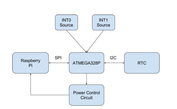
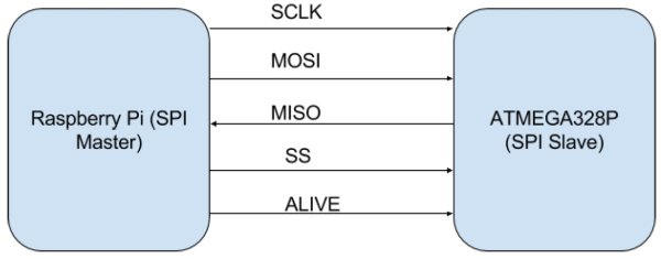
At a high level the design consists of four major hardware components. These are the Raspberry Pi itself, the ATMEGA328P, the RTC, and the Power Control Circuit. The Raspberry Pi wakes up when the ATMEGA328P provides it with power, and performs some action or series of actions based on why it was woken up. It then shuts itself down and alerts the ATMEGA that it can turn off power to the Pi. The Raspberry Pi and ATMEGA communicate with a custom protocol using SPI. The ATMEGA tracks the state of the Raspberry Pi and determines if it should be powered on or turned off. It determines this based on the time provided by the RTC and the state of its interrupt pins. The ATMEGA and the RTC communicate using I2C. The time interval and interrupts that should be able to trigger the ATMEGA to wake up the Raspberry Pi can be configured using a GUI on the Raspberry Pi. The ATMEGA then sets the state of the Power Control Circuit to control the power to the Raspberry Pi. Once configured and running, the system continuously cycles through a sequence of turning the Raspberry Pi on, letting it complete whatever application is desired, and shutting down the Pi again until the time interval expires or an interrrupt arives. A high level view of the system components is caputred in the block diagram below.
Hardware
ATMEGA328P
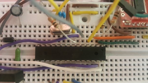
The first step in designing the project was choosing a microcontroller to control the power. The ATMEGA328P was used to control the power of the Raspberry Pi. This microcontroller was chosen because it can operate with far less power than a Raspberry Pi, is relatively inexpensive, and has extensive support and documentation because of its uses in the Arduino. Even though a stand-alone ATMEGA328P was used, all existing Arduino libraries could be used, making development much simpler. The ATMEGA328P also offers a diverse range of peripherals. It has external interrupts and is capable of communicating using both SPI and I2C, all of which were all necessary functions for this project. Below is a picture of the ATMEGA integrated into the system.
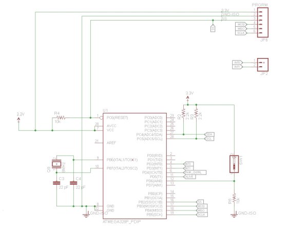
Next, the supporting hardware for the micrcontroller had to be designed. The ATMEGA328P was run at 3.3V and 8 MHz. In an Arduino it is typically run at 5V and 16 MHz, but this requires significantly more power. The lower frequency and voltage sacrificed performance to conserve energy, but the performance of the ATMEGA was still more than sufficient for this application. The ATMEGA only drew 3 mA while running, a significant improvement over the 210 mA that the Rasbperry Pi drew when idle. A schematic for the setup of the ATMEGA can be seen below.
Next, we had to determine how the Pi and the ATMEGA would communicate. Initially we planned to use I2C, but it proved impossible to have the Raspberry Pi act as a slave on an I2C bus and setting up a multi-master bus proved challenging. Instead, SPI was chosen for the link between the Raspberry Pi and the ATMEGA, so that I2C could be used exclusively for the RTC. The ATMEGA communicated with the Raspberry Pi using SPI, serving as the slave. The ATMEGA also connected to a GPIO pin on the Raspberry Pi that was configured to always output a high signal. When this pin went low, it indicated that the Raspberry Pi had shutdown, and when it went high again it indicated that the Raspberry Pi had turned back on successfully. This prevented any premature cycling of power, allowing the ATMEGA to track the exact state of the Raspberry Pi. The diagram below illustrates the connections between the Raspberry Pi and the ATMEGA.
Whenever the Raspberry Pi sent a request to the the ATMEGA, it would process the request and send back the appropriate response as specified by the communication protocol (see the Protocol section for more information). The ATMEGA could be configured to trigger wakeup of the Raspberry Pi from three different sources: a timer, external interrupt 0, and external interrupt 1. The timer could be set to various time intervals, and was constantly checked by querying the RTC for the current time and comparing that to the time the timer began. If the appropriate amount of time had passed since the Pi powered down, the ATMEGA would wake the Pi back up. External interrupt 0 and external interrupt 1 on the ATMEGA could also be configured to trigger a wakeup on a rising edge. Any type of hardware can be attached to these interrupt pins, it simply needs to be able to generate a rising edge at the desired time. For example, in the example application built for this project interrupt 0 was attached to a button and interrupt 1 was attached to a voltage divider with a photoresistor. This allowed the Pi to be woken up at any time by a user pressing the button or by increasing the light level on the photoresistor. These interrupts could be used for a wide variety of applications, such as waking the Pi up when something gets within a certain proximity or based on a variety of environmental factors, such as temperature or light. The ATMEGA controlled the power to the Raspberry Pi by simply changing the state of a GPIO pin that connected to the Power Control Circuit
Raspberry Pi
The Raspberry Pi 2 Model B was used for the project, though none of the functionality of the project relies specifically on special features of this model. Theoretically the project could be easily transferred to different models of the Raspberry Pi. The Raspberry Pi did not require any special hardware modification, but some of its GPIO pins had to be reserved to connect with the ATMEGA. The physical pins that were used on the Pi and their function is listed below.
| Raspberry Pi Physical Pin | Function |
| Pin 2 | 5V Input |
| Pin 6 | Ground |
| Pin 16 | Alive Signal |
| Pin 19 | MOSI |
| Pin 21 | MISO |
| Pin 23 | SCLK |
| Pin 26 | SS |
Power Control Circuit
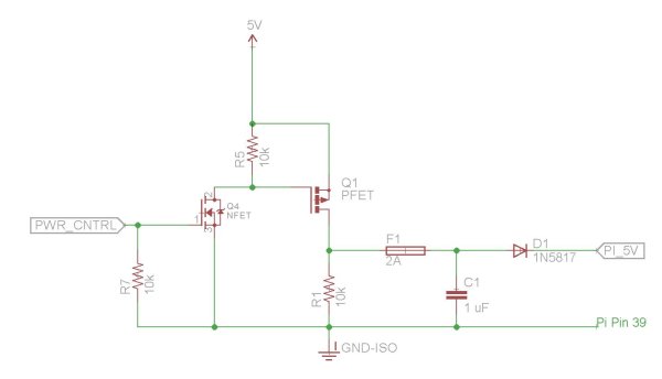
The Power Control Circuit allowed the ATMEGA to switch 5V to power the the Pi using a 3.3V signal from the ATMEGA's GPIO pin. Also, since power was being provided to the Pi through its 5V pin and bypassing the protection circuitry provided on the Pi itself, this protection circuitry was recreated. This consisted of a 2A quick-blow fuse, a diode to prevent reversed current flow, and a 1 uF decoupling capacitor. Two transistors were used to switch power to the Pi, one NFET and one PFET. The FQP30N06L was used as the NFET and the FQP27P06 was used as the PFET. Two of them were used for level-shifting and inversion, allowing a 3.3V signal to safely control 5V and allowing power to be connected only when the signal was high. A schematic of the power control circuit is shown below.
RTC
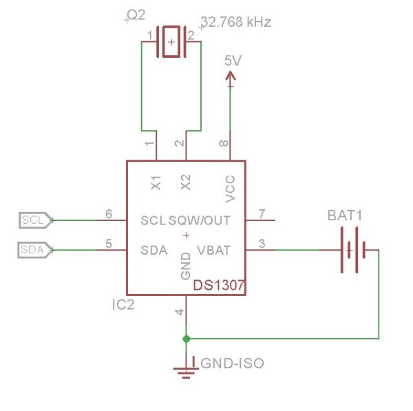
The RTC used was the DS1307, and more specifically the DS1307 breakout board from Adafruit was used for this project. The hardware setup for this component was extremely simple. The RTC was powered by 5V, but was able to communicate with the ATMEGA successfully using 3.3V logic. It communicated with the ATMEGA using I2C, and so connected to it through the SDA and SCL pins, which are pins 27 and 28 on the ATMEGA respectively. The SQW pin of the DS1307 was unused. A schematic of the RTC setup can be seen below.
Application and Interrupt Hardware
For demonstrating this project, some application specific hardware was used to give the Raspberry Pi something to do when it woke and to provide ways to trigger then interrupts. The Ping Ultrasonic Distance Sensor from Parallax was used with the Rasbperry Pi to simulate measuring river depth, and this simply required two GPIO pins on the Pi. A button was connected to interrupt 0 of the ATMEGA to serve as one of the interrupt sources, demonstrating the use of user input as a means of waking up the Raspberry Pi. A voltage divider that included a phototresistor was connected to interrupt 1 on the ATMEGA to demonstrate the use of environmental sensors to trigger interrupts. This setup would trigger the interrup ton the ATMEGA whenever the light levels on the photoresistor rose above a certain threshold.
Complete Circuit
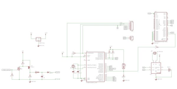
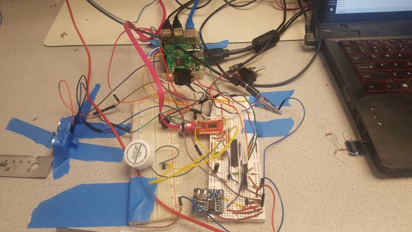
A full schematic for the hardware of the project is shown below. Note that this excludes the application specific hardware, such as the ultrasonic sensor and interrupt sources, as they are highly application specfic and were merely for demonstration purposes. The full circuit assembled for the demo is also shown below.
Software
GUI
For designing the GUI of the project, there were a few alternative options to Pygame which were considered. QtCreator was considered but its files had to downloaded and it takes 8 hours to compile it. With time constraints, Pygame was eventually chosen to be the tool for designing the GUI.
The 2 main requirements for the GUI were that the user could select a time interval and toggle the external interrupts. The toggling of the interrupts can be done by buttons on the GUI which are simple enough to implement. For the time interval, the initial plan was to have a textbox in which the user could enter minutes starting from a minimum of 1 minute to maximum of 1440 minutes (24 hours). The implementation for the text box turned out to be complex as every character which is typed out has to be displayed on every loop iteration. This means all the characters typed have to be stored and dynamically deleted if the user enters the backspace key. To be user friendly a cursor would also be required and this would further complicate the design.
Keeping the above complexity in mind, a drop down menu was selected for the time interval. Again a proper drop down would be difficult to implement fully in PyGame so a compromise was reached, there wouldn't be a drop down but the intervals could be iterated through by the user using the up/down arrow keys. The disadvantage of using this over the text box was that there could only be a limited options to select from for the user unlike the fully customizable minutes in the text box.
After getting all the desired functionality, the next step was to integrate the C++ code and the GUI. This turned out to be more difficult than was initially thought but an elegant solution was still found in the end. Now when the user presses the enter key for selecting the time interval, the corresponding C++ function has to be called for sending the config packets to the ATMEGA328P. Now C++ functions cannot be directly called in python scripts. So the options to do that were extending python which is adding support so that a C++ library could be imported or using the ctypes library to import C code (there is workaround for using ctypes with C++). Now for extending python, python wrappers have to be created in the C++ files for exporting them. These wrappers are available from the header file. After compiling the wrappers and C++ files a C++ library is created which has an extension of .so and can be imported to python. This library gave errors when the python script was run from the terminal. The ctypes library was also tried but gave errors too. Finally a solution was reached where the executable of C++ was called in the python script via the os.system call. For this a separate C++ wrapper file had to be created called guiMain.cpp which accepted command line arguments. These had to be made so that the wrapper could differentiate between the functionalities like the time interval, ping and the external interrupts.
When the time interval was successfully configured the Atmega sent a packet back which signalled success to the Pi. This packet was processed in the guiMain.cpp file and config success!!! text was written into a .txt file. The gui would poll this file and print Config Success!! on the screen when it read the text. After reading the text, it was deleted and the file closed. The success message on the screen lasted for 5 seconds. The Ping success message was implemented in a similar way described above.
Real Time Clock
The microcontroller receives the time interval in the form of seconds from the Raspberry Pi and stores it. When a power cycle is going on,the microcontroller reads the time since the epoch in seconds from the RTC which is also in seconds and compares it with the time configured. This is implemented as a poll in the main loop. When the time is greater than interval, the Pi is woken up.
Protocol Between the ATMEGA328P and Raspberry Pi 2
The communication between the Raspberry Pi 2 and ATMEGA328P happens through SPI. The protocol has been designed to have 9 types of packets, each of which are 11 bytes long being sent from the Pi to the Arduino and from the Arduino to the Pi. Now the ATMEGA328P has only a single SPI buffer and hence there is a unified interrupt for receive and transmit. To discriminate between receive and transmit, a start byte is used by the Raspberry Pi to enable a global variable in the Atmega which keeps track of whether a packet is being received or transmitted.
The packet is divided into a opcode byte and the payload bytes. The opcode gives information about what the packet is about. For example an opcode 0x01 corresponds to the wake response from the arduino to the Pi.
The different packets are given below with a short description for each:
The wake request packet is sent from the Pi to the ATMEGA328P and is basically a request for the reason for its wakeup. The start byte is 0xFE and the opcode is 0x00.
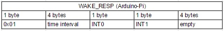
The wake response is the packet sent from the Atmega to the Pi in response to the wake request. The opcode is 0x01. Time interval takes up 4 bytes because it's a long variable at both ends. The INT0 and INT1 are simple toggle bits and hence take up 1 byte each. The rest of the packets are empty.

The sleep request is a packet which informs the Atmega that the Pi is going to shut itself down.
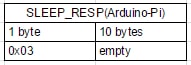
The sleep response packet is the acknowledgement from the Atmega in response to the sleep request.

The config request is the packet which is sent when the user has made a configuration change from the GUI. The “INT0 type” and “INT1 type” are currently not in use. They can be configured for falling, rising interrupts in the future. If only the time interval is being sent, then 0s are sent in all the other sections.
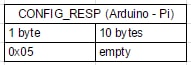
The config response packet is the acknowledgement from the Atmega from the Pi for the config request.
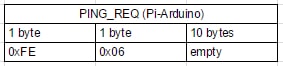
The ping request is the message from the Pi to the Atmega to check whether the communication between the two are working.
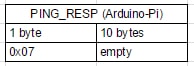
The ping response is the acknowledgement for the ping request. The junk packet is used by the master i.e. the Raspberry Pi to send clock pulses to its slave so that it can transmit its response. It is filled up with 0xFF.
ATMEGA328P
All software for the ATMEGA328P was created using the Arduino IDE. This was available since the ATMEGA328P was used, which is the micrcontroller used in the Arduino. Using this IDE allowed pre-existing libraries and chip configurations to be used, greatly simplifying development.
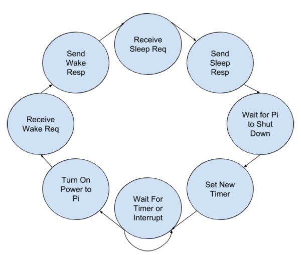
The ATMEGA328P tracked the state of the Raspberry Pi and the currrent time, and controlled the power to the Pi based on this. SPI communication was critical, and was handled by an interrupt. Whenever a byte arrived over the SPI interface the interrupt triggered and read and buffered the byte. After reading 11 bytes, an entire packet was received, so the packet was processed and the settings of the ATMEGA were changed if needed. This could include changing the length of the wakeup time interval or enabling or disabling the interrupts if it was a configuration message. The message also indicates the current state of the Raspberry Pi, showing where it is in its wakeup cycle. After parsing the packet, the ATMEGA prepares and sends an appropriate response to the Raspberry Pi. This SPI interface proved to be the most challenging part of the project to implement. Synhcronizing communication between the two devices proved difficult, and sending a slave response added complications, since the slave is always one clock cycle behind the master in terms of responding. Eventually, the interface was worked out and the protocol could be successfully exchanged.
The current time was constantly checked against the time for wakeup if the timing interval was enabled, and if it or an interrupt occurred the GPIO pin controlling the power control pin was set high. The whole process that the ATMEGA cycled through is captured in the diagram below.
Raspberry Pi
The entire software on the raspberry pi is written in C++ and is compiled using g++. The WiringPi library is used for getting the SPI transmit and receive functions. This SPI, as mentioned in the handshaking section is used for communicating with the Atmega328P. When the Pi boots up it sends a wake request to the Atmega asking the source for its wake up. This is mainly done to measure and store data for the application mapped to the source. The Atmega sends the source and if it's due to the time interval, then the “ultrasonic.py” script is called which does its measurements and appends it to a file only meant for the time interval source. Similarly there are separate log files for INT0 and INT1 interrupts. Once the measurements are done, the Pi prepares to shut itself down. Before doing that it sends a message informing the Atmega thats its going to sleep. Once the Atmega transfers the response, the Pi shuts itself down.
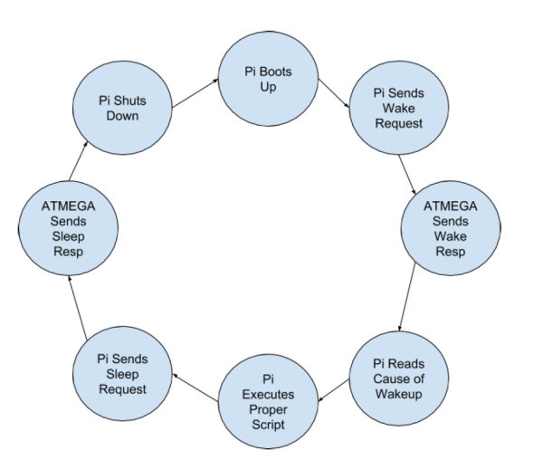
The snapshot of the cycle described above is shown below:
Parts and Budget
| Part Name | Price |
| Raspberry Pi 2 Model B | $35.00 |
| ATMEGA328P | $4.00 |
| DS1307 Breakout Board | $7.95 |
| 8 MHz Crystal | $0.75 |
| MCP1702 LDO Regulator | $0.48 |
| FQP30N06L | $0.95 |
| FQP27P06 | $0.95 |
| 2A fuse | $0.20 |
| 1N5187 Diode | $0.30 |
| Total | $50.58 |
Testing
Testing was carried out in various stages. First each portion of the hardware was tested in isolation. The Power Control Circuit was constructed and its output was measured using a multimeter to ensure that it did in fact switch with the appropriate input signals and that it could handle the needed output current. The ATMEGA328P circuit was then built and tested in isolation to ensure that the microcontroller could run properly at 8 MHz and 3.3V. This was tested using simple programs that were timing dependent, such as timed blinking of an LED, to ensure that the oscillator was set properly. SPI and I2C communication were first tested in isolation by connecting the ATMEGA328P and Raspberry Pi to oscilloscopes and verifying the waveform.
Initial software testing was simplified by begnning development using an Arduino development board. This isolated software issues from any hardware issues with setting up the ATMEGA328P. Various SPI verification scripts were created on the Raspberry Pi to check the integrity of its communication with the Arduino and try to get a qualitative idea of the packet loss rate. Use of the Serial ports on the Arduino was also a critical part of software testing, allowing a great deal of helpful debugging data to be printed out. This made finding and resolving errors much simpler.
Results
Overall, the project was successful. The goal of the project was to create additional hardware and a lightweight software framework for the Pi that enabled power management,and we believe that the final result closely matches that vision. We were able to implement all of the major functionality we had planned for. The ATMEGA was able to safely control power to the Pi without any damage or corruption of data. The ATMEGA was also able to accurately measure time and wake up the Pi at the appropriately configured intervals. Interrupt support was initially considered a stretch goal, but was successfully integrated and significantly increased the usefulness of the project. The Raspberry Pi also required no significant hardware modification, making the project more easily deployable for others. The Pi was able to successfully execute different scripts based on the different wakeup sources, and it was possible to easily modify the actions taken by each script, making it easy to implement a variety of applications. Theoretically, anyone should be able to deploy this on their Raspberry Pi with any application they wish with little modification, though it has only been attemped on one Raspberry Pi so far. The ATMEGA also did prove to use far less power when running by itself than the Pi did when it was idle, resulting in significant power savings. One area of the project that did not quite meet expectations was the build quality of the hardware. Their was not enough time to move the project to a custom PCB or even to solder onto a perfboard, so it is still only on a breadboard. Moving to a PCB would be ideal, as it would make the project much more reliable and improve its aesthetic.
Here's a video which describes our project in brief and shows its functionality:
Conclusion
The project met our goals, successfully reducing the power consumption of the Pi and making it easy to integrate a large number of different applications into this power management framework. Hopefully, this work can be used to help improve the lifetime of future projects and to allow the Raspberry Pi to be used in a wider array of applications, especially with low-power requirements. Learning how to integrate the Raspberry Pi with micrcontrollers such as the ATMEGA328P was an interesting experience, as they seem to be a pairing with a large number of potential applications together. Working out the communication and coordination between them turned out to be the most challenging aspect of the project, but was certainly worth it. Focusing more on the quality of the hardware early on would have significantly improved this project however, as starting work early on moving the hardware to a more permanent medium than a breadboard would have significantly improved its reliability and the look of the project.
Future Work
There are various extensions and improvements we would like to make the project. First and foremost, improving the quality of hardware would be ideal. We would like to create a custom PCB for the project, or even transfer it onto a Raspberry Pi Hat, to make it much more reliable and easier to use. We would also like to streamline some of the software setup for putting the project onto a new Rasbperry Pi. Currently it requires the files to be placed into a specific folder, and the user has to place the scripts they want to run into pre-define files. Having some form of installer and configuration interface for initial setup would help others to use this project more easily. We would also like to be able to configure the type of interrupts that trigger wakeup. Currently, only rising edges will trigger wakeup, but ATMEGA is capable of capturing various other interrupt types. Adding the ability to configure the type of interrupt that triggers wakeup would make integrating various interrupt sources easier. Finally, optimizing the boot time of the Rasbperry Pi would also be a good addition as currently it takes around 30 seconds for the Pi to boot, which means it is on for a longer time and consuming extra power. Shortening this boot time would improve the power savings.
Code Appendix
All code can be found at the GitHub page for GoodnightPi . To help sort through the files and figure out what they all do, the table below lists each file (not including executables and text files) and its purpose.
| Filename | Purpose |
| Full_Final | This is the sketch folder for the final code that was run on the ATMEGA328P. The code was developed using the Arduino IDE, so it currently exists as a .ino file. The Arduino IDE is required to read and compile it. |
| gui2.py | This is the python program that runs the PyGame interface for the GUI. Running this brings up the GUI itself. |
| guiMain.cpp | This program connects the GUI with the SPI interface, as the SPI interface is in C++. |
| INT0.py | This is the script that executes when a wakeup is caused by interrupt 0. |
| INT1.py | This is the script that executes when a wakeup is caused by interrupt 1. |
| on_led.c | This program runs at startup to set the Alive pin high. |
| raspi_spi.cpp | This is the file that controls the SPI interface to the ATMEGA. It includes functions that can be called to send any of the allowed packets to the ATMEGA, as specified by the protocol. |
| spi_checker.cpp | This file sends a series of SPI messages to the ATMEGA, checking the SPI connection |
| spitest.cpp | This file tests the SPI connection, sending a series of messages to the ATMEGA |
| startup | This shell script should be placed in the .bashrc so that it runs at startup. It runs on_led and wake_check |
| Timer.py | This is the script that runs when a time interval causes the Pi to wake up |
| ultrasonic.py | This is a script for testing the ultrasonic sensors distance readings |
| wake_check.cpp | This program always runs at startup. It checks if the Pi is in configuration mode, and if not asks why it woke up. It then runs the appropriate script and once it completes shuts the Pi down. |
Division of Work
Fred designed the power control circuit and the rest of the hardware connections between the Pi and the ATMEGA328P. Also built the circuit. Created code for SPI interface and helped design the SPI protocol. Created the wake_check code, as well as Timer.py, INT0.py, and INT1.py. Created startup script. Debugged ultrasonic sensor hardware. Helped to create website.
Amardeep initially wrote the code for RTC and got the interface of it with the microcontroller up and running. Created the GUI on the Raspberry Pi and integrated that python GUI with the C++ code. Wrote the script for interfacing the ultrasonic sensor with the Raspberry Pi and measuring the distance.
Read more: Goodnight Pi: Reducing Raspberry Pi Power Consumption