
It’s hard to imagine a smart house without smart lighting. Maybe it’s laziness, but the ability to turn a light on or off without walking over to the switch is a must-have, particularly once the lap is occupied by a sleeping infant. It’s tempting to just stuff a relay in the electrical boxes and control them with a Raspberry Pi or micro-controller GPIO. While tempting, get it wrong and you have a real fire hazard. A better option is one of the integrated WiFi switches. Sonoff is probably the most well known brand, producing a whole line of devices based on the ESP8266. These devices are powered from mains power and connect to your network via WiFi. One disadvantage of Sonoff devices is they only work when connected to Sonoff’s cloud.

Light switches locked in to a cloud provider are simply not acceptable. Enter Tasmota, which we’ve covered before. Tasmota is an open source firmware, designed specifically for Sonoff switches, but supporting a wide range of ESP8266 based devices. Tasmota doesn’t connect to any cloud providers unless you tell it to, and can be completely controlled from within a local network.
CERTIFICATIONS, LIABILITY, AND MORE
We’re well acquainted with some of the pitfalls of imported electronics, but one of the lesser known problems is the lack of certification. In the United States, there are several nationally recognized testing laboratories: Underwriters Laboratories (UL) and Intertek (ETL) are the most prominent. Many imported electronic devices, including Sonoff devices, do not have either of these certifications. The problem with this is liability, should the worst ever happen and an electrical fire break out. The Internet abounds with various opinions on the importance of the certification — a missing certification mark is somewhere between meaningless and a total hazard. The most common claim is that a house fire combined with non-certified equipment installed would result in an insurance company refusing to pay.
Rather than just repeat this surely sage advice from the Internet, I asked my insurance agent about uncertified equipment in the case of a fire. I discovered that insurance agencies avoid giving definite answers about claim payments. The response that came back was “it depends”: homeowner’s insurance covers events that are accidental and sudden. If a homeowner was aware that they were using uncertified equipment, then it could be categorized as “not an accident”. So far, the myth seems plausible. The final answer from the insurance agency: it’s possible that a non UL-certified device could result in denial of payment on a claim, but it depends on the policy and other details– why take the risk? Certification marks make insurance companies happier.
I also talked to my city’s electrical inspector about the issue. He commented that non-certified equipment is a violation of electrical code when it is hard-wired into a house. He echoed the warning that an insurance company could refuse to pay, but added that in the case of injury, there could be even further liability issues. I’ve opted to use certified equipment in my house. You’ll have to make your own decision about what equipment you’re willing to use.
There are some devices on Amazon that claim to have certification, but searching the certification database leads me to believe that not all of those claims are valid. If in doubt, there is a searchable UL database, as well as a searchable Intertek database.
SELECTING A DEVICE
So let’s review our requirements: We need a WiFi connected switch, supported by Tasmota, and either UL or ETL listed. So far, I’ve found exactly one device that fits these criteria. The EtekCity ESWL01 is certified by Intertek, relatively easily flashed to Tasmota, and even mounts on Decora plates. I’ve also received confirmation that Shelly has applied for UL certification, and is expecting that certification to be approved soon. Once they are certified, they will also make a good choice.

Flashing the switch is fairly straightforward, using a TTL serial connection. First, do not connect the switch to mains power while working on the internals. It can shock you, which is bad, but there is the very real possibility of feeding mains voltage into your serial port, which is worse. Instead, we’ll power the device with the power pin on the serial adapter. Note, this isn’t an RS 232 serial port, but a 3.3 V TTL level serial connection. I use the MM232R module, but any TTL serial adapter would work, including a Raspberry Pi.
To put the device in flashing mode, short GPIO0 to ground while connecting the power. There are several flashing tools, but Esptool seems the easiest, with a single command to flash. The official recommendation is to backup the factory firmware, zero out the ESP8266, and then flash the firmware. I’ve not found it necessary to take the extra steps, but if you run into problems, keep it in mind.
esptool.py write_flash --flash_size 1MB --flash_mode dout 0x00000 sonoff.bin |
I’ve used the released Tasmota binaries, but if you prefer to compile them yourself, instructions are provided. An advantage of compiling is that you can bake your WiFi information and other settings directly into the binary. If you don’t add WiFi information, the module will broadcast an open WiFi network you can connect to, in order to do your configuration. Set your WiFi information, and make sure to pick a useful hostname, as that’s what we’ll use to control the switch.
The unit will reboot, and should connect to your network. One last configuration step is to tell Tasmota about the device it’s running on. We’ll use the templates feature to define the important GPIOs.
{"NAME":"EtekCityESWL01","GPIO":[255,255,255,255,52,53,255,255,255,21,122,255,255],"FLAG":1,"BASE":18} |
Tasmota can be controlled via the web interface, with MQTT, or with a REST API, where commands are sent as HTTP GET and HTTP POST requests. We’ll use this REST interface. Once the switch is flashed and connected to your WiFi, re-assemble and install it using the manufacturer’s instructions.
A TOUCH SCREEN INTERFACE
We’ll start by building a simple PHP control interface, lights_api.php. This extra layer is important when isolating the IoT network, and means that only an HTML connection is needed to control everything.
<?php $curl_handle = curl_init(); if ($_POST["toggle"]) { $command = explode(".", $_POST["toggle"]); '/cm?cmnd=' . $command[1] . '%20Toggle' ); curl_exec( $curl_handle ); // Execute the request } if ($_GET["device"]) { '/cm?cmnd=state' ); curl_exec( $curl_handle ); // Execute the request } curl_close( $curl_handle ); |
This lets us make a simple HTML request, like “lights_api.php?device=entry-light-1”, and receive a JSON object with the current status of the device. A POST message allows toggling the switch state.
You may remember that we’re using the Raspberry Pi touchscreen as one of our primary interfaces. This interface is only 800 x 480, which is quite a design challenge for a user interface. I’ve sketched a rough floorplan of my house using Libreoffice Draw, and exported it as an SVG. Over this image, we’ll draw icons to represent the controllable lights.
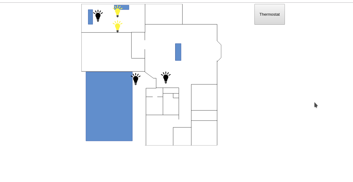
<div style="width:700px; margin:auto; margin-top: -4px;"> <div style="float:right; float:top;"> <button onclick="window.location.href = 'index.php'" style="padding:25px 15px; margin-right:25px;">Thermostat</button> </div> <div style="height:470px"> <img style="position:absolute;" height=470px src="House-Blueprint.svg"/> <img class="light" style="position:absolute; margin-top:0px; margin-left:95px;" height=50px id="office-light-1.POWER3" onclick="button(this)" src="unlit.svg" /> <img class="light" style="position:absolute; margin-top:15px; margin-left:30px;" height=50px id="office-light-1.POWER2" onclick="button(this)" src="unlit.svg" /> <img class="light" style="position:absolute; margin-top:50px; margin-left:95px;" height=50px id="office-light-1.POWER1" onclick="button(this)" src="unlit.svg" /> <img class="light" style="position:absolute; margin-top:225px; margin-left:155px;" height=50px id="entry-light-2.POWER" onclick="button(this)" src="unlit.svg" /> <img class="light" style="position:absolute; margin-top:220px; margin-left:255px;" height=50px id="entry-light-1.POWER" onclick="button(this)" src="unlit.svg" /> </div></div><script> updateAll(); let updateTimer = setInterval(updateAll, 10000); function button(caller) { var xhttp = new XMLHttpRequest(); xhttp.onreadystatechange = function() { update(caller); } xhttp.open("POST", "lights_api.php", true); xhttp.setRequestHeader("Content-type", "application/x-www-form-urlencoded"); xhttp.send("toggle=" + caller.id); } function update(element) { var switchInfo = element.id.split("."); var xhttp = new XMLHttpRequest(); xhttp.onreadystatechange = function() { if (this.readyState == 4 && this.status == 200) { var state = JSON.parse(this.responseText); if (state[switchInfo[1]] == "ON") { element.src = "lit.svg"; } else { element.src = "unlit.svg"; } } }; xhttp.open("GET", "lights_api.php?device=" + switchInfo[0], true); xhttp.send(); } function updateAll() { document.querySelectorAll('.light').forEach(function(light_element) { update(light_element); }); }</script> |
There is a bit of trickery going on here. The img elements contain the entire definition for each switch. The updateAll() function iterates through all of the elements of class “light”, fetching the status of each switch and updating the graphic. The ID of each img contains the hostname of the switch, as well as the indicator of which GPIO we’re interested in, allowing support for devices that control multiple lights. The update() function is run on each img element, using the information baked into the ID to request the switch state from our PHP interface.
We’ve also defined the onclick of each img, giving us our touchscreen functionality. After the toggle request has been sent, we also force an update on that light, in order to keep the interface synced. I’ll leave it as an exercise for the reader to write out the img elements with PHP and add a database back-end.
And with that, we have a simple touchscreen interface to control lighting. It works on a cell phone or desktop, so no more waking the baby to turn off the lights. It’s also a simple interface for further programming. Want the hallway lights to come on when the front door is opened? Just add an HTTP GET request to the handler script.
With a Raspberry Pi in every room, and the lights under control, I’ve got a good start toward a smart house. I have a few items left on my wish list, but I want to hear from you. What haven’t I covered that you think is an indispensable smart-house function?
Source: HACK MY HOUSE: UL CERTIFICATION AND TURNING THE LIGHTS ON WITH AN ESP8266