
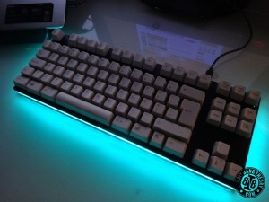
Hello fellow ‘instructablers'! In this instructable I'll present you a brand new project that I’ve just completed. In fact, I’m using the project itself to write this instructable. I present to you the amazing, the fantastic, the magnificent… HacKeyboard!
What is HacKeyboard?
It looks like a computer keyboard, and it is, but not an ordinary one. It’s story and hidden functions add a lot more to it. “Under the hood” you’ll find that this keyboard has:
SMK Alps Mount switches: Yep, this is an NKRO (N-Key Roll Over) fully mechanical keyboard with good old SMK Alps Mount switches. A single switch beneath each key gives you an amazing tactile and audible feedback of every keypress just like the old good keyboards from the 80s.
Compact size: it has a tenkeyless format.
Special commands to record up to 12 macros: if you work with spreadsheets and often have to repeat the same stuff in a lot of cells, fear no more because HacKeyboard will let you save up to 12 different key sequences, each up to 150 key presses. You’re a gamer and you want to shoot, jump, move to the side and reload with just one click? HacKeyboard has got your back on that; You’re a programmer and want to write your if, while, for structures automatically? HacKeyboard can do that too! Oh, and it’s all done by key commands without any software required. It’s all built-in!.
Internal Keylogger: Yup, You can log whatever you/someone who uses your keyboard writes. What can you do with what they write? I’ll leave that to your imagination! Just remember that with great power, comes great responsibility!
Internal USB hub: It has an additional micro USB connector to plug in one of those recent micro USB pen drives or any USB device by using a USB OTG cable.
Internal 8GB secret storage: well… now that I’m telling this it’s not secret anymore HacKeyboard has an internal 8GB USB flash drive that will never be seen by your computer unless you press a specific key combination. Perfect to store your secret photos/videos/documents.
4 LED illumination modes: HacKeyboard has a ring of RGB leds around it that can work in four different modes: static, LED chaser (KITT style), rainbow and breathing. Also, you can customize your preferred color just by using keystrokes. Once again, no specific software needed. If you don’t press any key for a while, breathing mode is automatically activated.
Fully open hardware/software: you can reprogram the microcontroller to change key combinations, add illumination modes, do whatever you think of (Challenge: add a mod to play 1D Pong in HacKeyboard).
Internal EEPROM: any macro or color configuration you make is stored in an internal EEPROM. You can unplug your keyboard and everything you saved will still be in the keyboard the next time you use it.
USB-HID: It is a common USB-HID device, which means it uses a generic HID driver and works on Windows, Linux and Mac.
Oh, and should I mention that it was built using parts from old keyboards, making it very cheap to make? 🙂
In the video you can see it in action! 🙂
Step 1: How do those special functions work?
As mentioned in the previous step, any of the special functions of the keyboard can be used without requiring any special software. Everything is done using key combinations. On the top right corner of this keyboard there is/was the Pause/Break key, which maybe 99,9% of the current computer users never used nor know what is it used for. Well, I know what it can be used for but I don’t use it, so I replaced it with a Power key, the key that makes the magic happen in this keyboard. Once you press Power, the keyboard enters a power mode where you can use some other keys to use the special functions of the keyboard. Here’s the list of key sequences to use the special commands:
Save macros:
< Power >, < S > , < Fx >: This will make the keyboard activate the power mode and save a macro for position < Fx > (Fx can be any key from F1 to F12). Anything you type after this key sequence will be recorded for position < Fx >. To quit macro recording modejust press < Power >.
Play macros:
< Power >, < Fx >: This will enter the power mode, play the macro stored in position < Fx > and exit the power mode.
Activate/Deactivate keylogger:
< Power >, < L >: This will enter power mode, activate/deactivate the internal keylogger and exit the power mode.
Play the keylogger log:
< Power >, < K >: This will enter the power mode, play the keylogger and exit the power mode.
Activate/Deactivate the hidden internal 8GB USB storage:
< Power >, < P >: This will activate/deactivate the internal 8GB USB storage and exit the power mode. It is advisable to first safely remove the USB device in the computer operating system.
Changing colors:
< Power >, < R/G/B >, < +/- >: This will change the amount of Red/Green/Blue in the ring of LED’s. If you press < + > you will increase the chosen color component and if you press < – > you will decrease it.
After modifying the color you can cancel the operation by pressing < Power > and the LED ring will restore the previous default color or you can store the chosen color as the new default color. There are 4 colors that can be customized by pressing different keys:
< C >: When you press this key you will chose the current color as the default color shown during normal keyboard usage.
< D >: When you press this key you will chose the current color as the default color shown during power mode.
< E >: When you press this key you will chose the current color as the color shown to signal that you entered the macro recording mode but have not yet chosen a position.
< 3 >: When you press this key you will chose the current color as the color shown when you entered save mode and have chosen the macro recording position. Anything you type when this color is shown, is stored in the chosen macro position.
To terminate the color configuration and return to normal keyboard usage, just press < Power >.
The video above shows all the functions in detail.
Step 2: Why make a keyboard when I could simply buy one? (optional reading)
Picture of Why make a keyboard when I could simply buy one? (optional reading)
Some time ago I was given a small lot of old computers and computer peripherals and among the peripherals there was an old IBM Model M2 keyboard with buckling spring switch mechanism and Portuguese layout. The “click, click click” of the keys just made me remember the old keyboards that almost sounded like old typewriters. If you were born in the 80s or before you know what I’m talking about. The keyboard had a PS2 connector, which I plugged into an old desktop computer. It worked perfectly and I thought my usual desktop keyboard was just going to be replaced as soon as I manage to buy a USB to PS2 adapter. However, once I got one and tried it I became disappointed because the “<>” key didn't work. I got another converter and no luck either. Maybe those converters aren't just made to be used with keyboard with Portuguese layout.
In the meantime, I started to investigate a little more about keyboards and found out that there are communities like GeekHack and Deskthority with endless discussions about mechanical keyboards: new products, vintage keyboard collections, keyboard mods, DIY keyboards, etc. Who would have guessed? While browsing those forums I just saw some amazing tenkeyless compact mechanical keyboards and then I just decided that I wanted to get one! However, I soon became disappointed to find out that at that time there wasn't a single Portuguese tenkeyless keyboard being manufactured. It seems like the Portuguese market is to small to be profitable enough for manufacturers. Even when talking about normal mechanical keyboards with Portuguese layout, I think there are only 3 or 4 and only half of them have a real Portuguese layout since the others seem to have been adapted from another language because some keys have a different size and a few symbols are in different positions. Oh!… and there’s a common thing with mechanical keyboards… they’re pretty expensive (from 90€ upwards)! So, I found myself in the situation that I really wanted a product that I couldn't buy anywhere at that time. It seemed like the end of the road, but it wasn’t… We live in an era where information is freely available online and digital fabrication tools are making their way into the homes of common people. As a Maker, the solution as simple: “I’ll just make my own”, I decided.
Step 3: What's the difference between mechanical keyboards and normal keyboards? (optional reading)
Picture of What's the difference between mechanical keyboards and normal keyboards? (optional reading)
Most keyboard that you find on stores nowadays (basically all of them except the high-end gamer products) use a silicone membrane with a silicon dome under each switch, having each dome a small contact that will trigger the keypress once you push the key down. After some time of usage the contact gets wasted and sometimes you have to push the key down harder to make a keypress.
Differently, mechanical keyboards use actual, physical switches underneath the keys to determine the user has pushed a key. When you press a key, you press it's switch down. When you press the switch down, the keyboard sends a signal to the PC telling it that you pressed that key. These switches are far more durable than the rubber domes and have two very important features: a ‘click' sound that provides direct feedback to your ears and a mechanism that automatically pushes the switch down once you push it to a certain point. Unlike rubber dome keboards, where you just know that the key has been pressed when you look at the screen, with mechanical keyboards you have tactile and audible feedback that let you know that the switch has been pressed for sure. There are some claims that due to this direct feedback, you can type 30% faster with mechanical keyboards. There are also other claims that say that you get less ‘finger fatigue' with mechanical keyboards because the mechanical switches do part of the pushing down force for you, but you probably only need to worry about this if you're a programmer or professional gamer.
Among mechanical keyboards you can find several types of mechanical switches, being the most common nowadays the Cherry MX switches. You can find them in several variants, having each a different type of audible and tactile feedback. These are the switches you find in expensive high end gaming products that are available in the stores. Since they are still manufactured you can buy individual switches and keycaps in several online stores.
Another type of switch that was very common was the ALPS and the SMK Alps mount switches. You can find these in many old keyboards. Some of the keyboards that I know that have them are the Siig Minitouch, the Monterey K108, and the Focus-2001. I'm sure there are many more, but these are just the ones I know of at the moment. I actually like more the SMK Alps mount switches than the Cherry switches. However, unless you find them on old keyboards I never found any store that sells the individual switches nor keycaps for these kind of switches.
There are also other variants of mechanical switches like the Topre, the buckling springs, and others, but I'm sure you can find more information in the links below if you're interested in this topic 🙂 .
More information here:
http://www.pcworld.com/article/242037/mechanical_keyboard_faq_pick_the_right_switch.html
http://www.pcworld.com/article/240939/mechanical_keyboards_should_you_switch_.html
http://lifehacker.com/how-to-choose-the-best-mechanical-keyboard-and-why-you-511140347
http://deskthority.net/
https://geekhack.org/
Step 4: Safety Information
Picture of Safety Information
Now that you know a little bit about mechanical keyboards, let's get into building one from scratch 🙂 As with all projects, safety first!
Please pay attention to this step, it is very important, if not the most important step in this instructable. 🙂 During this process you will need to use some tools and chemicals that may be dangerous and harmful if you don't take appropriate safety measures.
While using any electrical or manual tools, wear protection gloves at all time. Surely you don't want to lose a finger or cut or burn yourself.
Protection glasses should also be used, specially if there is the possibility of pieces of hot plastic or metal flying around during drilling or cutting.
While using corrosive chemicals, always use latex gloves and make sure you have good ventilation. Doing this outside or just next to a window should be fine. If you happen to have access to a protected chamber with fumes extractor, even better.
Step 5: Tools and mechanical parts
Picture of Tools and mechanical parts
For this project you will need various tools but you don't need to have all of them. If necessary it may be easier and cheaper to just pay for some cutting or etching services. Here's the list:
Keyboard parts:
Old keyboards with mechanical switches and fitting keycaps. In this tutorial I'll be using the SMK Alps Mount switches from a Monterey K108 and the ALPS compatible keycaps from an old NGS keyboard (model unknown).
Protection:
Latex Gloves
Protection glasses
Workshop gloves
Soldering:
Soldering Iron with fine tip (1mm max)
Side cutters
Pliers
35x15cm double sided PCB
Solder
Desoldering pump
Multifilar wire scraps
Soldering flux (optional, but recommended)
Desoldering braid (optional)
Hot Air rework station (optional)
Isopropyl alcohol (optional)
Machining:
Saw
Drill Press
CNC Machine (Note 1)
0.7mm and 1mm drills
Dremel
3mm cutting bit for Dremel
Metal files
Chemicals:
Muriatic acid / Hydrochloric acid (33%)
Hydrogen Peroxide (10 vol)
Epoxy Glue
Others:
Sharpie (Note 1)
Clothes Iron (Note 1)
Glossy Magazine (Note 1)
Plastic trays
Sponge
Clear vinyl or tape (Note 1)
Laser printer (or go to some copy store and order prints in glossy photographic paper) (Note 1)
Stainless steel sponge
Craft knife
Scissors
4 pcs 350x150x3mm cast acrylic plates (Note 2)
Carbon fiber vinyl
Computer
10pcs 10mm M2 screws
10pcs M2 nuts
2 pcs 5mm PVC rod
2 pcs big rubber feet
2 pcs small rubber feet
Digital Caliper
Hot Glue gun
Heat gun or hair dryer
A4 toner transfer sheets
Screwdrivers
PIC Programmer (in my case Kit 149BC PIC Programmer)
USB to serial TTL converter (optional)
Braided USB cable (optional)
Multimeter
Power supply
Software:
FreeCAD
HeeksCAD (Note 1)
LinuxCNC (Note 1)
PIC programmer software (in my case MicroPro)
Note 1: In case you have access to a laser cutter, all the equipment with this note are not necessary because the laser cutter can be used to replace them all. If you have access to one, the project will be a lot easier, faster, safer and will come out a lot more perfect. Throughout the instructable I'll mention where a laser cutter would be specially useful. A laser cutter is a huge plus in this project! Having one would have been a great help.
Note 2: In case you have access to a laser cutter, you can use extruded acrylic, which is cheaper than cast acrylic. The laser cutter will cut it just fine without any melting problems.
Step 6: Electronics Parts
Picture of Electronics Parts
For this project you will need several electronic parts. All of them are very affordable and although most of them are SMD parts do not be afraid of not having the required skills to solder them. It's actually quite easy 🙂 I find it even easier and faster than soldering through hole parts. Later in this instructable I'll also provide some references to other instructables that contain some very good tips and tutorials on how to do it.
Here's the component list:
1 x Microchip PIC18F4550 TQFP (datasheet) – this 8-bit MCU has integrated USB and was chosen to be the brain of the keyboard. I chose it because I had a few of them laying around and I knew that there were some libraries to make USB HID devices with it;
1 x Microchip 24AA512 SOIC EEPROM (datasheet) – to store all the key sequences and logging;
1 x Maxim MAX682 SO-8 3.3V input to 5V Regulated Output Charge Pump with 250mA output current (datasheet) – according to some information I found online, most USB pen drives and computer mice require supply currents smaller than 100mA, so 250mA should be more than enough;
27 x WS2812B PLCC4 RGB LEDs (datasheet) – these RGB LEDs are just the best thing you can think of in matter of addressable RGB LED illumination;
Cheap chinese USB hub – Getting the hub and disassembling it to get its working PCB is actually much cheaper than just buying a chip to make the USB hub on board, so I just hot glued the hub PCB to the main PCB and soldered some wires between both boards;
131 x 1N4148 through hole diodes;
1 x 20MHz low profile crystal;
2 x micro USB connector;
89 x ALPS or SMK Alps mount switches (taken from an old Monterey K108 keyboard);
1 x pcb momentary switch;
23 x 10K 0805 SMD resistor;
3 x 1K 0805 SMD resistor;
1 x 100K 0805 SMD resistor;
1 x 330nF 0805 SMD capacitor;
2 x 22pF 0805 SMD capacitor;
1 x 100nF 0805 capacitor;
1 x 220uF 1210 SMD capacitor;
1 x 2.2uF 0805 SMD capacitor;
1 x 1uF 0805 SMD capacitor;
1 x 10uF 0805 SMD capacitor;
1 x 5×1 2.54mm male headers;
1 x 8GB USB Flash Drive;
I bought most of the stuff on ebay. In case you're a student you can use your school/university email to order free samples of the Microchip and Maxim parts, which are the ‘less cheap' parts.
Step 7: Gather old keyboards
Picture of Gather old keyboards
To make a mechanical keyboard the first things you have to get are the switches and the keycaps.
I started looking for switches and keycaps online but once again I ran into some problems to source the components. The only switches that I could find were the Cherry switches, which can be bought in several varieties (no click, more clicky, less clicky, etc.) but they’re pretty expensive (I don’t recall the exact prices but it was about 1.5$ per switch, plus shipping) and a keycap set could cost about 40$ plus shipping and I couldn’t find a keycap set with portuguese symbols printed on them. I could try to buy a set with blank keycaps and then try to engrave them in my TheMaker2 CNC but the amount of money I would have to spend plus the time I would have to work on it made me give up on the idea of buying every single part. It would even be cheaper to buy a complete mechanical keyboard with portuguese layout just to get the Cherry mechanical switches and printed keycaps to make the tenkeyless keyboard.
The solution for this, as mentioned in this step's title is to gather old keyboards.
You can get lucky and get a keyboard that has both or you might need to get some until you get the switches/keys/colors/layout you want for your keyboard. There are various places where you can get them:
Ask your family: maybe some of your relatives work at some company where they have loads of old equipment to throw away. They'll even thank you for taking away their ‘trash' 🙂 !
Ask your friends: the same described above applies;
Ask around in some companies where you might know someone;
Ask at your school/university;
Try to go to electronics recycling facilities. In some they won't let you take anything, in others they will negotiate a price with you and in others you might get lucky and take the keyboards for free;
Go to junkyards: some collect electronic equipment to sell to recycling facilities by weight.
Go to garage sales: there are lots of stories of people getting vintage keyboards that are worth 50$ for as low as 1$ 🙂
As I mentioned before, I managed to get an old Monterey K108 (I actually got two of these 🙂 ) with SMK Alps Mount switches and an old NGS keyboard with the layout that I desired (Portuguese) and ALPS compatible keycaps. All of them for free! 🙂
Step 8: Desolder the switches
Picture of Desolder the switches
This step is very easy to do 🙂 Just remove any screws from the old keyboards, open it and then desolder all the switches using a soldering iron and a desoldering pump. Be careful no to break the pins. I noticed they can break if you bend them too much. In one of the pictures I show you how it is inside. This switch was not “clicking” so I decided to open it up to see what was wrong. It turned out to be a small metal piece that was not bent as it should. I just fixed it, closed it and it started clicking again 🙂
Step 9: Retr0bright the keycaps (optional)
Picture of Retr0bright the keycaps (optional)
This is an optional step that you can do if the keycaps from the old keyboard are too yellow. The plastics of the housing of many electronic devices contain a fire-retardant component called Bromine that is responsible for the “yellowing” of the plastics when in contact with light and oxygen. That's why if you keep your vintage electronics closed in a box they won't change color as much as if they are exposed to those two components. In a simple way, this component sort of removes oxygen from the plastic to prevent fires and by removing oxygen the plastic changes color.
It turns out that some clever people who love vintage computer came up with a solution to reverse the plastics back to their original color. In a simple way, they found a way of returning the oxygen to the plastic.
There are several variations of the recipe and although I didn't need it for this keyboard I have tested one of them with success in some keys from other old keyboards. Here's what I did:
Went to the grocery store to pickup hydrogen peroxide, one of those oxi-detergents and corn starch;
(Important!) Put my latex gloves on;
Cleaned all the keycaps with a toothbrush and dish washing detergent;
Mixed them until I had a white paste;
Put the keycaps in a plastic tray and poured the white paste over them;
Covered the tray with transparent thin film;
Put it outside for a few hours so that they were exposed to UV light.
After a few hours, cleaned the paste from the keys and observed the result 🙂
The keycaps that I used for this test were only slightly yellow but even so I noticed improvements.
Since the keycaps are very small I also tried putting them into a transparent water bottle with hydrogen peroxide exposed to UV light for a few days and I also noticed some improvements on the color of the plastic keys.
I only provided you with a very short description of the process. If you think this step is necessary for your keycaps I recommend you to read this great instructable: Retr0bright, how to turn a yellow Gameboy white again: The EASY way!
Step 10: Start designing the keyboard case
Picture of Start designing the keyboard case
The keyboard case design was inspired in some other keyboard designs I saw online. I decided to go for a simple case with 4 layers of plexiglass/acrylic: top layer, 2 middle rings and bottom layer. The top layer need to be machined to have square cutouts to fit all the switches. Using a digital caliper I measured all the different keycaps and the switches dimensions and then I started designing the top layer in FreeCAD, which is a great open source 3D design software. Once I finished the top layer, I designed the middle rings and the bottom layer, which were a lot simpler. The bottom layer is just the same as the middle rings but without the inner cutout. You can get my FreeCAD files here and modify them to suit your own ideas. If you want you can also get the keyboard layout in vectorial format here.
Once you finish your design, you'll want to export the designs as .svg or .dxf files, which are the files used by CAM (Computer Aided Manufacturing) software.
Step 11: Cut the acrylic plates
Picture of Cut the acrylic plates
Show All Items
To cut the acrylic plates you have to options
Go to some workshop to get them Laser cut: this is the best option since you will get perfect plates with no trouble at all with crystal clear edges and perfect dimensions. You can even use extruded acrylic which is cheaper than cast acrylic;
Go to some workshop to get them CNC cut: this is also a good option but you'll want to stick to cast acrylic and the edges won't come out crystal clear (which is not a bad thing at all, since it will diffuse the LED lights).
In my case, I used my homemade CNC, TheMaker2 (instructable here).
I started by importing the .svg files from the previous step into HeeksCAD and generated the toolpaths using the Profile operations (HeeksCAD files here). Then I placed the cast acrylic plates in my CNC machine and put hot glue around them to hold them steady in the CNC table. Since it would be the longest CNC machining I had ever done and I didn't have any leftover acrylic to retry in case something went wrong, I defined the toolpaths to make the cut in several small Z steps (0.5mm) and a slow feedrate. The machining of the front plate alone took 6 hours. The middle and bottom layers were much faster. It took some time but the resulting plates were great! 🙂
Remember, if you try to follow the same procedure, make sure you get cast acrylic, not extruded acrylic. Cast acrylic will be machined just fine, without melting. On the other hand, extruded acrylic will melt around your cutting bit, which is something you do not want to happen.
Having access to a laser cutter would have reduced the machining time to just a few minutes 🙂
Step 12: File the inner corners of the square cuts
Picture of File the inner corners of the square cuts
Since I used an endmill with a 1.5mm radius, the inner corners of the cutouts for the squares also had a 1.5mm radius. To fit the switches the corners had to make a sharp 90º angle. To fix this I used a small file in all the corners (yes, I had to manually file 89×4 = 356 corners 🙂 )
Step 13: Test if everything fits together as planned
Picture of Test if everything fits together as planned
At this point I tested all the parts I had ready so far to see if everything was fitting as planned and no mistakes were made. I inserted all the switches and keycaps in their places and stacked the four layers of acrylic to check for any errors. I also got a first vision of how it would look and feel and was pretty excited with the result so far 🙂 Everything was perfectly aligned and looking good 🙂
When you reach this point, if something is not correct, fix it and only then proceed to the next step.
Step 14: Glue the middle layers
Picture of Glue the middle layers
I proceeded to glue the two middle layers with super glue. In this step it is very important to be careful to glue them perfectly aligned. If I had 6 mm acrylic available I could have made a single ring instead of two, which would avoid gluing and would look a little better.
Step 15: Drill the mounting holes
Picture of Drill the mounting holes
After having the acrylic layers glued I marked some spots to drill the mounting holes in all the layers and used the drill press to drill 2mm holes only in the bottom layer and in the two middle layers. I didn’t do this step in the CNC because I didn’t have any 2mm cutting bit at that time. I made a total of 10 holes:
4 in the corners, 3mm away from the outer edges;
2 in the middle, 3mm away from the top and bottom edges;
4 holes at 1/4 and 3/4 of the longer side, also 3mm away from the top and bottom edges.
If you use a laser cutting service, you may put the holes in the design before cutting and you can skip this step. Remember, do not drill the top layer at this point, only the bottom and middle layers.
Step 16: Open pockets for nuts in the top layer
Picture of Open pockets for nuts in the top layer
In the top layer I used the Dremel to make some pockets to fit some M2 nuts at the same positions mentioned in the previous step. The remaining space around the nuts was then filled with epoxy resin, which also held the M2 nuts in place. To prevent the glue from getting into the thread of the nut, I placed the screw inside the nut before applying the glue.
When the glue was completely dry I removed the screws and filed the excess glue until the surface was leveled with the acrylic. Afterwards, to remove any remains of glue from the thread of the nut I used a small drill an manually rolled it inside the nut.
Step 17: Bore the holes in the bottom layer
Picture of Bore the holes in the bottom layer
I didn't want the heads of the screws to show outside the acrylic plate since I didn't find it aesthetically pleasing. To fix that I used the drill press to open little bores for the heads of the screws in the bottom layer. When doing this you must be careful because you can go only at 2 mm of depth. Otherwise you'll just drill through the acrylic plate, which is something you don't want.
Step 18: Add support clips to any keys you think might need them
Picture of Add support clips to any keys you think might need them
When I previously pre-assembled the parts I verified that the Enter key could jam a little bit if pressed in the corners. Since the key is big and the switches are not made to be used with side forces, it could be uncomfortable to use. To solve that I decided to add some clips to the bottom of the key to apply a stabilizer, just like the ones used for big keys like the Space-bar and the Right Shift keys. This clips are used to fit a piece of metal that distributes the force applied to long keys, so that the force is also applied vertically, even if you press the key in the corner. To make the clip holders I used a piece of rigid PVC and small files and saws. I tried my best to make them similar to the ones in the Right Shift key that you can see in the photos. I did them manually because they are very small and I had no other way of doing them. If I had a 3D printer at that time I would surely design and 3D print the clip holders. If I had a laser cutter, I could make them laser cut as well in no time. To make the metal clips I used a paperclip and some small pliers to bend them accordingly. When ready, I glued them to the bottom of the keycap with epoxy glue.
Step 19: Place key stabilizer clips into the top plate
Picture of Place key stabilizer clips into the top plate
At this point it was time to place the key stabilizer clip holders in the top layer, which were removed from the original Monterey K108 keyboard.
To place this clip holders in the top layer, once again I used the Dremel to open some pockets in the approximate positions, placed the clip holders inside and filled them with epoxy resin. To make sure the clip holders stayed in the correct position, I mounted the switches and keycaps for these keys with the metallic clips in place while the epoxy resin was drying.
Once the glue dried, I removed the switches and used a craft knife and some small files to remove the excess glue.
Step 20: Place guide tubes for the Space-bar
Picture of Place guide tubes for the Space-bar
Since below the space-bar there were to aligning plastic pieces, I also had to make some small guide tubes for them, which were also glued in place with epoxy glue. The guide tubes were made of some PVC rod drilled in the middle. To make sure they were glued in the correct place, I placed the space-bar key in place, pressed it a few times to align the guide tubes and then let it the glue dry. Once dry, I removed the key and the switch.
Step 21: Apply the carbon fiber vinyl
Picture of Apply the carbon fiber vinyl
Finally it was time to make it pretty, instead of a mess of scatched acrylic with holes and glue 🙂 .
First I assembled the hole case and use an electric sander to remove small misalignments between layers. I wanted it to be perfect! 🙂
So, to hide all the Dremel made pockets and epoxy glue, I used carbon fiber vinyl to cover the top and bottom layers. To apply the carbon fiber vinyl I used a heat gun to heat it and then slowly stretched it until I covered the acrylic layers. A hair dryer could also be used, but I didn’t have any in my home lab 🙂 .
When applying the vinyl you have to be very patient, specially in the top layer, which has some protruding parts. Take it slow, heat it a little bit and stretch it well and if you see bubbles appearing, pull it a little bit back and retry. Take your time and be gentle. If you’re careful you can even wrap it around the edge to the back of the plate without any wrinkles.
Once you manage to wrap it around the edge, take your craft knife and cut the excess in the bottom of the plates. In the top plate, also use the craft knife to cut away all the 89 squares.
Step 22: Assemble the case and apply rubber feet
Picture of Assemble the case and apply rubber feet
It was finally time to assemble the case and apply rubber feet to the bottom. The rubber feet I used can be found in any hardware shop. I used three small rubber pads in the bottom and two big rubber pads in the top to give the keyboard a little slope.
Step 23: Put the keys in place, grab a sandwich and appreciate what you've made
Picture of Put the keys in place, grab a sandwich and appreciate what you've made
If you are following this instructable and building your own keyboard, now is the time to put the switches in place, grab a sandwich and a drink and appreciate your own work while you regain energy for the electronics part 🙂 The mechanics part of the keyboard is mostly done and there's only one little thing left to do after the electronics part is ready.
Step 24: Selecting the components, designing the schematic and PCB
Picture of Selecting the components, designing the schematic and PCB
In the beginning of this instructable I provided a list of components that will be used in the electronics part of this project.
Just as extra information, the list of components provided is the result of three iterations of the schematic and PCB. To reach the final design I designed three versions of the schematic, three versions of the PCB, manually fabricated three huge double sided PCBs, including drilling, vias and soldering components. It took me some time to do all of this, but I didn't give up and reached a final working design.
Gladly for you, you won't have to go through all of it since now the working design is fully open source and you can just use it it or work on it to make your own modifications (different switches, different layouts, extra features, etc.)
As previously mentioned, I used KiCAD for the electronics and PCB design. All the KiCAD project files and schematic and PCB in PDF format can be downloaded in my Github.
Brief explanation of the electronics: HacKeyboard has a single microcontroller, the PIC18F4550, which has built-in USB. The word ‘microcontroller' and the reference ‘PIC18F4550' may seem complicated or strange but it is basically the same kind of thing as the ATMega328 that you find on Arduinos, but from a different manufacturer, with a different architecture and different built-in features. Having that said, the microcontroller is responsible for managing and controlling everything on the keyboard:
Reading the switch matrix: Taking into account that a keyboard is a big matrix of switches, each column and each line are connected to a different IO (input/output) pin on the microcontroller. The microcontroller turns each column on at each time, one by one and reads the logic levels in all the lines, evaluating which switches in that column are pressed. Then it turns that column off and proceeds for the next one. This happens several times per second. It is a very fast process that is always running on the microcontroller. Once the key presses are evaluated it outputs the respective characters via USB;
Controlling the hidden USB Flash Drive: The flash drive is powered via the MAX682, which is a 5V charge Pump regulator that has a ‘Shutdown' pin. To activate or deactivate the USB flash drive, the microcontroller activates or deactivates this pin, turning it on or off.
Saving macros and key log: In the circuit there is a 24AA512 Serial EEPROM (64K x 8 bits) which is a memory that is used to store all the macros and the key activity log. When in saving modes, the microcontroller, which is connected to the memory via a serial protocol (SPI) sends to specific memory positions the keys that must be stored. This memory holds the data even if you turn disconnect the keyboard. In the default firmware each macro position can store up to 150 bytes and the rest of the memory is used by the key logger. This can easily be modified by just changing some address values in the provided source code.
Controlling the WS2812B RGB LEDs: The microcontroller is also responsible for controlling the RGB LEDs. These LEDs have their own serial protocol where a ‘0' is represented by a pulse with a certain timing and a ‘1' is represented by another pulse with a different timing (check the datasheet for timings). The LEDs have a build in 3 byte memory where they store the 3 values for Red, Green and Blue. These values must be in a range from 0 to 255. They also have a built-in shift register, which allows them to pass on information to the next LEDs. If you only have 2 WS2812B LEDs, you connect your microcontroller to the data input pin of only one of them and you connect the data input pin of the second one to the data output pin of the first one. Then the microcontroller will have to send 6 bytes, 3 for each LED, starting from the second LED (more distant in terms of connections). The first LED will pass on the information to the second one.
Step 25: Making the PCB
Picture of Making the PCB
This part of the project was one of the most time-consuming and frustrating. I’ll tell you why. The PCB is too big. Too big to order from a PCB manufacturing service because it is too expensive and too big to make with the usual homemade PCB methods. However, with a few attempts and a lot of patience it can be done. I used the toner transfer method. This method is fairly simple:
Print your PCB in glossy paper in a laser printer;
Clean your PCB from any grease;
Put the printed PCB upside down on top of the PCB;
Apply clothes iron for a few minutes;
Soak the PCB with attached paper into water and carefully remove the paper;
Verify that the toner tracks are attached to the PCB;
Put it into a corrosive solution like ferric chloride or hydrochloric acid with hydrogen peroxide until the non-protected copper is etched;
Remove it from the corrosive solution and clean it water;
Remove the toner with a stainless steel sponge;
Drill the PCB holes
Done!
I could go on trying to explain it in detail, mentioning all the tricks and tips, it but instead I'm going to recommend you to follow some other great instructables that other users have made and that are very, very well explained:
PCB Making guide
Two Sided PCB Using Toner Method
Most Simple Home-Made PCB by Toner Transfer
Toner transfer no-soak, high-quality, double sided PCBs at home
Easy, Consistent & Cheap Toner Transfer Method for Single & Double Sided PCBs
If you follow these guides, you'll understand how it works. there's no way you can go wrong 🙂
However this is not a usual PCB and I run into several problems:
Since the PCB is bigger than an A4 sheet, you have to print it in 4 parts;
Since the PCB is double sided you need to align all 4 parts;
Since the PCB is too big you need to get a powerful iron. If you use a weak iron it won’t melt the toner enough to make it stick to the copper since the PCB simply acts as a huge heatsink; If you have two irons, use two irons. If you have three… you know what to do. 🙂
When removing the paper some small parts of the toner traces would also get removed. I had to fix them using a sharpie;
The etching process has to be carefully controlled. Since I would have to waste a lot of etchant to get the whole PCB covered, I used a sponge to etch specific parts of the PCB (learned it in this great instructable). This takes time and patience but allows you to monitor the etching process, and stop it and fix it if necessary.
I used hydrochloric acid (33%) with hydrogen peroxide(10 vol) as the corrosive solution and had to replace the corrosive solution several times since the amount of copper to be etchet would quickly saturate it. I usually use 50% acid with 50% hydrogen peroxide.
In total I had to make 3 attempts to get the PCB done but then I finally got one that was good enough to continue with the project.
Here are some very helpful tips:
Important: Do it in a very well ventilated area and if possible use a mask for your mouth/nose, don't forget the latex gloves and the protective glasses! You don't want acid in your eyes 🙂
Important: When mixing the acid with the hydrogen peroxide, always pour the hydrogen peroxide first. This way if any drops of etchant jump out while you pour the acid, they will have a smaller concentration of acid.
Do it in 4 steps:
Toner transfer the first part;
Toner transfer the second part, carefully aligning it with the first, cover the other side of the PCB with tape or vinyl, etch it and clean it;
Drill 3 or 4 guide holes;
Toner transfer the third part, carefully aligning it with the first or second;
Toner transfer the fourth part, carefully aligning it with the remaining three, cover the already etched side with tape (both sides) or vinyl, etch it and clean it;
Closely watch the corrosion process and if the toner is coming out somewhere, stop the corrosion, clean it, dry it, fix the traces with a sharpie and then resume;
To align between parts, cut an X in a regions where one of the parts is on top of the other and fold the tips outwards. Then align the traces of the PCB with the lines in the folded parts. When using guide holes, use a light on the other side of the PCB to see if the two layers are aligned.
Or… all of these problems can be avoided in a very simple alternative method:
Get a Laser cutter
Paint the PCB with black spray paint;
Import the inverted PCB files into the laser cutter software;
Use the laser to etch away the paint in areas where the copper must be removed;
Repeat for the other side;
Etch the whole PCB at once without any worries, since the black paint won't come out easily;
Done! You just got your best double sided PCB ever!
NOTE: Some of the photos in this step are from one of the early revisions of the board, but they serve the purpose of showing the PCB making process.
Step 26: Drill all the holes
Picture of Drill all the holes
This step will also take some time but is fairly easy to do, specially with a small bench drill. Take the 0.7mm drill, put it into the drill press and proceed to drill all the vias and all the leaded component holes. It helps if you go into KiCAD and print a PCB without any traces, just with holes and then mark every hole as you drill the PCB. Since there are lots of holes to be done, it's easy to skip a few if you don't do this. I provide all this helpful files in postscript format here.
Once finished, take the 1mm drill, put it into the bench drill and proceed to drill all the switch holes and also the programming connector holes near the micro USB ports
Step 27: Connect all the vias
Picture of Connect all the vias
This step will also take some time, but again, is easy to do. Take a piece of scrap multifilar wire and remove the insulation. Then take 2 or 3 thin wires, roll them around each other and then insert them in a via hole and solder them in both sides. Cut the excess and repeat for all the via holes in the PCB. Once again, having a sheet with all the hole locations printed helps keeping track of which vias have already been connected.
Step 28: Solder all the components
Picture of Solder all the components
Now is the time to solder all the components. I recommend following the component placements in the KiCAD PCB file and starting with the SMD components like the processor, eeprom, charge-pump regulator, micro USB ports, SMD resistors and capacitors, WS2812B LEDs and only then proceed for the diodes and the programming connector. Make sure you solder the WS2812B LEDs in the correct position, since theire orientation can be tricky to figure out. Look at the datasheet to confirm.
The diodes must be soldered on both sides of the PCB, since their leads are also used to connect traces in both sides of the PCB.
If you're wondering why we need the diodes, they are necessary to prevent something called ‘ghosting'. Ghosting is when you press two keys and the keyboard doesn't know which keys you're pressing. Why and when does this happen? Well, the keyboard is a big matrix of switches, and as all matrixes, is composed of lines and rows. If there are no diodes, when you press two switches on to different lines and two different rows, when the processor reads the matrix there are four key possibilites, instead of 2, and it can't tell which ones are correct.
Let's consider an example: assuming you have a QWERTY keyboard, image you press ‘Q' and ‘S'. If there are no diodes, the processor will not know if you're pressing ‘Q' or ‘W' and also doesn't know if you're pressing ‘A' or ‘S' because ‘Q' and ‘A' and ‘W' and ‘S' are in the same columns and same rows. The diodes prevent this from happening since they isolate each column or row from each other.
Soldering tip: for SMD components like the microcontroller, the EEPROM and the Charge Pump controller you can use a technique called drag soldering that is very well explained in this instructable: How to Solder SMD ICs the easy way!
Step 29: Prepare the USB Hub
Picture of Prepare the USB Hub
We're almost done with the electronics 🙂 Now it's time to prepare the USB Hub. You should try to find a hub similar to the one shown in the pictures on ebay since they have a low profile and a small PCB with no soldered connectors. They're very cheap (probably the cheapest), very common and very easy to find. Here's the step by step of what you have to do at this point:
Open the case carefully. It should be very easy with a flat screwdriver or a craft knife.
Take a picture of it so that you can later verify where all the cables should be soldered. In case you don't, it should be similar to the one you can see in the images.
Desolder all the wires that connect to the USB connectors.
Solder new wires, with the same colors (so that you don't go wrong) on the host side (port H);
On the client side you have signals for 4 USB ports but we'll only use 3: for one of them you should solder all 4 wires with the correct colors (port A), in another you should solder all three except the red one (port B) and in the other just solder the green and the white (port C). Leave the fourth port without any wires. Remember the port letters H, A, B and C, since they will be referred in the next step.
Put a thin layer of hot glue just to make sure they don't come out.
Step 30: Solder the USB hub
Picture of Solder the USB hub
Now that we have prepared the USB hub, let's attach it to the PCB. Find a nice spot without any solder blobs and glue it to the PCB with hot glue. If you think it's necessary, you can put a layer of tape below to prevent any short-circuits.
After gluing it in place, the wires should be soldered on the right place:
If you're looking at the PCB from the microcontroller side, the 4 wires from the host side (port H) should be soldered to the 4 pins near the right micro USB connector (look at the images for help and color ordering);
Considering the same view, the set of wires that only has green and white (port C) should be soldered to the two pins next to the microcontroller;
The set of wires with four wires (port A) should be soldered to the 4 pins near the other micro USB connector;
The set of wires with three wires (port B) will be used to connect the flash drive.
Using hot glue, put all the cables in safe positions, glued to the PCB, except the ones from port B.
One of the photos clearly shows all the connections and you just have to do the same thing 🙂
Step 31: Prepare the USB Flash Drive
Picture of Prepare the USB Flash Drive
This step is very simple, but once again you must be careful:
Using the craft knife, pliers and flat screwdrivers try to open the plastic case and remove the flash drive PCB from it.
Carefully desolder the USB connector.
Solder a red wire to the VCC pin (see picture for help)
Step 32: Solder the USB Flash Drive
Picture of Solder the USB Flash Drive
In this step it's necessary to find a small spot to glue the USB drive to the PCB. In this case, since we're dealing with a double sided PCB I recommend putting a piece of electrical tape or kapton tape in the keyboard PCB to prevent short circuits. Then you have to:
Glue the USB drive on top of the tape with hot glue and then solder the three wires from port B of the USB hub to the GND, D- and D+ pads on the USB drive.
Solder the other end of the red wire that you soldered to the VCC pin of the flash drive to the pin near the Charge-pump regulator (see picture for help).
Put all the cables in safe positions, glued to the PCB with hot glue.
The photos in this step clearly show where each wire should go, in case you have any doubts 🙂
And you're done with the all the wiring and component soldering! 🙂
Step 33: Developing the code to make it all work
Picture of Developing the code to make it all work
In this step you won't have to do anything. I'm just writing about it so that you know how the code was made.
I decided to use JAL to develop the firmware since I didn’t have a lot of time to get it working for Lisbon Mini Maker Faire. JAL, or Just Another Language, is a high-level language for a number of Microchip PIC microcontrollers that precedes the Arduino framework. As a curiosity, Massimo Banzi, one of the Arduino co-founders, was an early JAL developer. Another reason why I decided to try JAL was that there was a USB HID device sample code in JALlib that ended up making the first steps int
For More Details: HacKeyboard – open hardware mechanical keyboard