
Unhappy with a headlight modulator I purchased, I decided to make my own. Even though it would be a trivial programming project to use an Arduino Teensy or similar to do this, I decided to do it the “old fashioned” way, using a 555 timer. The 555 is a clever chip; not only will it supply the oscillator for the flashing effect, it has a reset pin that can be used to force the output to a known state (low) when (other circuitry tells it that) it's dark outside. Thus the headlight will be steady “on” after dark, flashing in daylight. The 555 is happy to run directly off the nominal 12 volt vehicle electrical system, so no voltage regulator is needed. The 555 is almost immune to electrical system noise, so no worries about your Arduino code going off into the weeds if there's a spike from the electrical system.
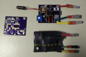
The first photo shows three boards from OSH Park; one bare (as it comes from OSH Park), one stuffed, and one stuffed and covered in heat shrink for installation on my motorcycle (inside a fairing). These are an earlier revision that lacks R11 and R12.
Note: Click on the pictures to embiggen.
Note: this circuit is for a DC, negative ground motorcycle. This shouldn't be a problem, most of you have probably never seen a positive ground motorcycle, but in general, beware British motorcycles made before about 1980, and also some (again, old) motorcycles and scooters had AC lighting systems, and they won't work with this either.
The 555 is configured as a “nearly” square wave oscillator, with R7, R8, and C2 controlling the frequency. The frequency must be about 240 +/- 40 cycles per minute, or about 4 Hz according to the US law governing headlight modulators. The reason that the output isn't a perfect square wave is that the charge current for C2 is through R7 and R8, but the discharge current is only through R8, so C2 discharges faster than it charges. The closest to 50% duty cycle will be achieved when R7 is small compared to R8, but if R7 is too small, then R8 will pull too much current from the power rail when it's discharging C2. 3.9KΩ vs 150KΩ says that the duty cycle error only amounts to 2.5 percent, so duty cycle is close enough to 50% for this application.
Pin 5 of the 555 allows modulating the 555, and we don't need that, so we just hang a 10nF cap on pin 5 as recommended by the data sheet.
The output of the 555 isn't robust enough to drive a headlight, so we use a P-MOSFET (Q3) to do the switching. The chosen MOSFET has an RDSon of 0.02 Ω or 20 milliohms, so it barely gets warm powering a 5A headlight filament. It also has a max drain current (Id) of 52 Amps, so it'll handle pretty much any headlight you care to use on a motorcycle. (Power = I squared R, so for the MOSFET is 25 * 0.02 = .5 watt, which results in negligable heating for a TO-220 package.)
R12 is there to prevent parasitic oscillations by Q3.
For more detail: Headlight Modulator for Motorcycle