
1 Introduction
1.1 Acknowledgement
We would like to thank Dr. Thomas Daniels for the assistance in researching, developing and guiding us
throughout the two semesters we have worked with him. He has been an amazing resource as we
worked through challenges on the project. We appreciate all the time and effort that Dr. Daniels has put
into our senior design project.
1.2 Problem Statement
Many people decorate their homes and other objects like Christmas trees with a set of lights. However,
current holiday lights are limited by not being customizable and are usually only one design. In order to
decorate an arboreal display we must first visualize the display and lay the lights accordingly. Thus, our
team has decided to tackle this problem of being able to create complicated light displays in a simple
manner.
1.3 Problem Solution
Our solution to this problem combines both hardware and software. The idea is for users to set up RGB
LED lights on a tree and then upload patterns to the string of lights. We will use an Android App to send
pictures of the RGB LED lights to the Web App, from which a model of the LEDs will be created. The Web
App will send the pattern to the Raspberry Pi which will then power the lights. The user will be able to
select many different types of colors/patterns.
1.4 Intended Users and Uses
The intended users for our holiday lights are people who are interested in programmable LED lights, as
well as anyone interested in using technology around their homes. The user must have an Android
smartphone in order to capture the images and have the ability to add the Raspberry Pi to their
network. The intended use for our holiday lights is for display on a tree displayed in a home and/or
indoor environment. It is not currently suitable for outdoor display.
1.5 Operational Environment
The current operational environment for these lights is intended to be an indoor environment, safe from
any harsh weather conditions such as rain, wind, or snow.
2 Project Design and Implementation
2.1 Project Design
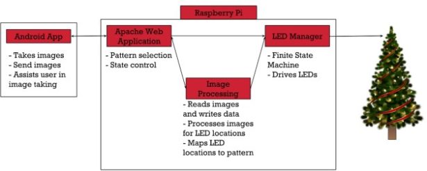
There are two major components to this project. The first is the Android App, and the second is the
Raspberry Pi (Model 3B). The Android App communicates directly with the Web App to start the
calibration process as well as take and send images of each individual lit LED on the tree. The Web App is
used to select patterns for display and controls the state of the LED Manager. The Image Processing
software takes the images sent from the Android App and processes the images to find the LED
locations. It will also convert the LED locations into a format for custom image patterns. The LED
Manager is a finite state machine that drives a pattern onto the lights via GPIO PWM output.
2.1.1 Functional Requirements
❖ Raspberry Pi PWM controller sends RGB values to LED
❖ Android App takes pictures for calibration process and sends them to the Web App
❖ Web App selects what patterns to display on the tree
❖ Image Processing finds LED locations and converts them to pattern creation format
❖ Web App controls state of LED Manager by creating and deleting .lck files
❖ LED Manager drives lights
2.1.2 Non Functional Requirements
❖ Android App must be responsive and easy to use
❖ Calibration process must be energy efficient to limit battery use
❖ Web App must control state of LED Manager while maintaining mutual exclusion
❖ System must be able to run for long periods of time without fail
❖ Image processing must have equal number photos for each side as they relate to # of LED’s
2.1.3 Constraints
❖ Raspberry Pi 3 Model B processor and storage limitations
❖ Android only mobile application
❖ Android App and Web App must communicate via WiFi
2.1.4 Hardware Specifications
❖ Raspberry Pi 3 Model B
❖ 3x WS2811 LED String of 100 LEDs
❖ 3.3V to 5V Level Shifter (SN74AHCT125N)
❖ 12V30A Power Supply
2.1.5 Software Specifications
❖ Java
❖ Android Studio
❖ Python
❖ RPi WS281x Python Library
❖ PHP
❖ Apache2 Web Server
➢ HTML, CSS, JS
2.2 Raspberry Pi
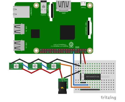
A Raspberry Pi Model 3B is used to host the Apache2 Web Server and run the Web App, LED Manager,
and Image Processing. The Raspberry Pi powers a 3.3V to 5V level shifter via its 5V DC power output (Pin
04). The level shifter takes the 3.3V logic output of the Pi (Pin 12, GPIO 18) and converts it to 5V logic,
which is then fed into the data line of the WS2811 LEDs. The WS2811 LEDs are powered by the 12V 30A
power supply.
2.2.1 Web App
The Web App is responsible for selecting patterns to display, controlling the state of the LED Manager in
order to update the current pattern being displayed, as well as serving as a means of communication
between the Android App, Image Processing, and LED Manager during the calibration process.
2.2.1.1 User Interface
The application’s user interface (UI) presents the user with three different web pages to choose from: a
Home page, an About page, and a Pattern Selection page. The Home page presents the user with a brief
breakdown of the components chosen for our project. The About page contains basic information about
the project as well as each team member. Finally, the Pattern Selection page allows the user to choose a
pattern to display from a set of premade patterns. The Pattern Selection page triggers a php script
(pattern_select.php) to update the pattern being displayed when one is selected.
2.2.1.2 Scripts
The Pattern Select script (pattern_select.php) checks what state the LED Manager is in by attempting to
create a lock file (running.lck). If the script succeeds in creating the lock file, this means that the LED
Manager is currently in the Idle State. Otherwise, if the script fails to create the file the LED Manager is
currently in the Running State.
If in the Idle State, the script will copy the selected pattern data into the current pattern text file
(current_pattern.txt) and then delete (unlink) the idle lock file (idle.lck). By doing so the LED Manager
moves from the Idle State to the Running State, reading from the updated pattern data.
If in the Running State, the script will create the idle lock file (idle.lck) and delete the running lock file
(running.lck), forcing the LED Manager into the Idle State. Once in the Idle State, the selected pattern
data is copied into the current pattern text file (current_pattern.txt). Next, running.lck is created and the
idle.lck is deleted (unlinked), sending the LED Manager back to the Running State, reading from the
updated pattern data.
The lightLED.php script is utilized by the Android App to pass a LED index through to the Calibrate.py
script to light the LED at the given index. This allows the Android App to easily make a request to
individually light each LED during the calibration process.
The upload_file.php script is utilized by the Android App to upload the pictures taken during the
calibration process to the Raspberry Pi. These files are then later accessed by the Image Processing
software to identify and log the specific locations of each LED.
2.2.2 Image Processing
The Image Processing software hosted on the Raspberry Pi is in charge of analyzing images taken by the
Android App to find LED locations. This process is written in python using two main libraries available,
these are the scikit-image and OpenCV 2 libraries. There are two important steps that occur within the
program those being the image analysis and then the coordinate comparisons. The program can be
configured to process images by each side but would require all sides to be processed before comparing
LED locations. The reason for this being that the computation time of image processing is long and
therefore it can be running while the photos of another side are taken.
The image analysis process starts with loading a folder containing all the images to one side of the tree
(each image is labeled respectively to the LED). The first image in this list is of the tree with none of the
LEDs lit up and is respectively labeled the unlit image. So the actual process to find the LED starts by
subtracting the unlit image from an image holding a single lit LED and this is shown below.
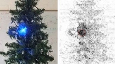
This subtraction process is done using the scikit-image library to output an image that scores the
differences between pixels and creates a new grayscale version. So by taking an image of the tree with
the LED on and off we get a difference image. Then using a OpenCV library we can detect when simply
put, a blob or collection of darker pixels. So this application has parameters that can be changed in order
to better calibrate the detection process. The reason for this being that depending on the settings for
the image taken or what LED is on you have varying levels of noise. This blob detection software is
looking at the grayscale image and finding groups of darker pixels which should equate to LED locations.
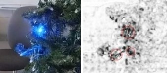
Now if the software were to find multiple LED locations then it would find the “center of mass” between
these points. The full calculations behind giving each point a mass wasn't implemented but could be
based on the amount of darker pixels at each grouping.
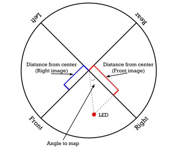
After finding all the LED locations for a singular side of the tree the process is then repeated for each
side, and upon having all of the data the LED location calculations can start. Using Figure 6 and starting
our calculations using the front of the tree we take the distance from the center from either the right or
left side depending on the direction from the front side. In this case the front had a positive number
from the center so we take the right sides value for that LED. Then using those values the angle is
calculated and is converted into a value from 0° – 360° based on the location.
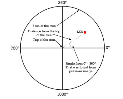
Upon finding a value between 0° – 360° we then use Figure 7 to map the LED locations for wrapping
around the tree. So one quadrant of the circle is a cone which can be theoretically made into a tree and
then displayed. So if someone were to color an image into one quadrant it could be displayed on the
tree. Then in order to rotate an image or something on the tree the angles for every LED which should
be displayed on the one quadrant can be increased or decreased by one in order to shift the
pattern/image displayed.
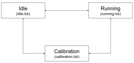
2.2.3 LED Manager
The LED manager is a finite state machine written in Python that controls and drives the WS2811 LEDs
through the use of the RPi WS281x library. The LED Manager consists of three states: idle, running, and
calibration. In each state, the LED Manager polls for the existence of a .lck (lock) file that represents the
current state that it is in. The LED Manager does this by calling os.open() on the respective lock file
(idle.lck, running.lck, or calibration.lck) with the flags os.O_CREAT (create file if it does not exist) and
os.O_EXCL (error if create and file exists). The state of the LED Manager is completely controlled via the
Web App, so any file that the LED Manager creates represents a state that it is not currently in and is
immediately deleted before checking for the next state. If the creation of the lock file fails, the LED
Manager catches the OSError and then begins to perform the duties specified by that specific state. The
duties for each state are as follows:
❖ Idle
➢ Intermediate state, LED Manager polls for existence of idle.lck
➢ If idle.lck is created by LED Manager, leave Idle and check for Running/Calibration
➢ If idle.lck is not created, LED Manager sleeps for a short duration and polls again
❖ Running
➢ Performance state, LED Manager polls for existence of running.lck
➢ If running.lck is created by LED Manager, leave Running and check for Idle/Calibration
➢ If running.lck is not created, LED Manager forks
■ Parent process polls for state changes
■ Child process runs strip.runPattern()
➢ The class lightstrip.py is imported and used in the child process
■ An Adafruit Neopixel strip object ‘s’ is created in the class
A pattern is read from the current_pattern.txt file into a pattern list
■ Using s.setPixelColor(index, color) and s.show() functions, the patterns are
displayed on the LEDs
❖ Calibration
➢ Intermediate state for LED Manager, Web App handles processing here
➢ If calibration.lck is created by LED Manager, leave Calibration and check for Idle/Running
➢ If calibration.lck is not created, LED Manager sleeps for a short duration and polls again
To drive the LEDs, the LED Manager imports a Python class lighstrip.py, which implements the RPi
WS281x library. When ran, the LED Manager creates an object of the LightStrip class called strip. Strip is
then used to run the functions within the class. Within this class, an object of an Adafruit_Neopixel LED
strip is created and initialized. Once this is done, the pattern is read in from current_pattern.txt and
loaded onto the lights with s.setPixelColor(index, color) and s.show() functions.
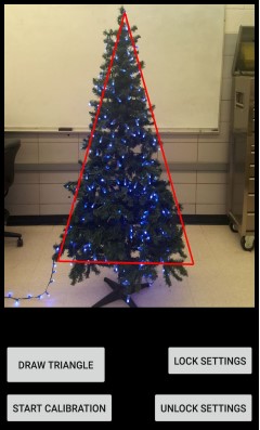
2.3 Android App
The Android App is responsible for initiating the calibration process, as well as sending calibration
information to the Web App. The user interface (UI) of the application presents the user with four
buttons/options: Draw Triangle, Lock Settings, Unlock Settings, and Start Calibration.
By default, the UI opens with a red triangle already displayed; this is to help the user maintain the
location of the tree as it will need to be rotated to get the location of the LEDs in 3D space. The Draw
Triangle button is there to allow the user to define their own triangle if they cannot get their tree to line
up with the starting triangle. All the user has to do is tap the 3 corners of their tree after pressing the
button to establish a new triangle.
Lock and Unlock Settings perform opposite functions; they are used to either lock or unlock the auto
focus and auto exposure. This is to help maintain parity between images if the brightness of the LEDs in
their current environment causes these values to vary such that it makes image processing more
difficult/inaccurate.
Start Calibration is the main function of the Android App. On press, it sends a HTTP request to a PHP
script on the Web App to create a lock file that sets the state of the LED Manager. Once in calibration
mode, the Web App will wait for more HTTP requests from the Android App which specifies the index of
an LED to be lit. Once the Android App receives a HTTP 200 status code from the Web App that the
specified LED is lit up, it calls a TakePicture method that takes a picture and saves it to the device, and
then calls the same method again after updating the index. When the index reaches the last LED, the
requests will stop and then all the images will be sent.
3 Testing
3.1 Web App
We tested the Web App by using it’s intended features in conjunction with the other parts of our
project. One of the features of the Web App is to select the colors to display on the tree. This can be
easily tested by checking if the selected color on the Web App matches the color on the RGB LEDs. We
can test the Start Calibration feature of the Android App by checking if the lock file on the the Web App
is created and also if the Web App sends the correct 200 HTTP response code.
3.2 LED Manager
The first stage of testing for the LED Manager was testing to ensure that it could change states based on
the presence of the respective lock files for each state. This was done by having the LED Manager run
without any existing lock file and analyzing its terminal outputs to see if it was looping through each
check properly.
The second stage of testing for the LED Manager was ensuring that each individual state performed the
required state duties. For Idle and Calibration, this stage was simple due to the fact that these two states
simply poll for the existence of their respective lock files. For the Running state, the testing involved
checking if the state could easily be changed by the Web App, checking that the processes forked
properly and that the parent process could kill the child process, as well as ensuring that each method
within the LightStrip class worked properly.
The final stage of testing for the LED Manager was acceptance testing of the patterns displayed on the
lights. Predetermined patterns of LEDs (such as all red, all green, all blue, etc.) were loaded onto the
lights to ensure that the brightness of the lights was at an acceptable level. Flashing patterns were also
tested to ensure that the refresh rate of the tree was at an acceptable level and did not cause eye strain
after different lengths of time observing the tree.
3.3 Image Processing
The code behind image analysis started out by testing different strategies to go about doing the process.
Initially the goal was to have the process run on the Android application and therefore be running in
Java rather than python. This decision changed upon trying to get OpenCV to work on android and it
wasn't going as planned. Because of this, the program turned to purely python and testing started by
working through OpenCV applications. The start was designing simple OpenCV scripts to find the LED
locations with just the lit LED image. This was done by loading our image from disk followed by
converting it to grayscale and smoothing/blurring it to reduce noise. The brightest regions in the blurred
image were LED locations and parameters to find those groups are used. Then to test this application
images were thrown at it to find out the accuracy of its LED locations. This relatively simple program is
how the process of image analysis started and was tested. Over time the software changed to where it is
now and the testing process is relatively the same. One of the additional applications added to the
software was by giving the option to select the LED location as the process analysed each image. This
allowed for the ability to tweak the parameters as application was running.
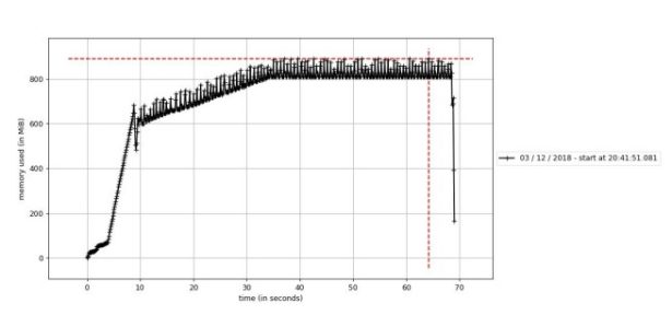
One of the methods to test the program was to use an application for looking at memory usage. The
software used was python Memory_Profiler program that plots the memory usage over time. Now the
goal of image analysis was to do it as fast as possible and therefore the test was to check if the software
was maxing out. Shown in.
3.4 Android App
Unit and validation testing was conducted for each feature of the Mobile Application. For the Draw
Triangle feature, the unit testing was done manually by creating three points in which a triangle would
be formed. The Lock and Unlock settings feature was tested by making sure the lighting conditions
matched the respective setting chosen. This feature was relatively easy to test as the picture would be
clear once the right setting was found. The final feature, Start Calibration, was tested by checking if the
lock file was created. If the calibration was successful, then the lock file will be created and the Web App
will wait for more HTTP requests from the Android App.
All of these features were also tested using validation testing. After each feature was developed and unit
tested, the feature was shown to the rest of the group and our client. Each individual group member
would provide suggestions, and the comments and concerns of the client was also taken into
consideration.
By running frequent tests and taking suggestions from group members and our client, we made sure
that the application is as bug free as possible so the application in the future could be built upon.
4 Results
In section 4.1 Current Progress, the current functionalities and scope of each individual component are
listed.
In section 4.2 Future Progress, additional functionalities are listed that could be beneficial to implement
upon continuation of this project. Items listed in this section include functionalities that were part of the
initial scope of the project, but were not completed and/or started due to various circumstances.
4.1 Current Progress
4.1.1 Web App
The Web App currently has these functionalities:
❖ Successful control of states of LED Manager to select and update selected patterns
➢ This is accomplished through a php script that creates and deletes lock files to maintain
mutual exclusion of pattern files when updating patterns.
❖ Runs php scripts in the background for Android App to:
➢ Request the illumination of a specific LED by index for calibration purposes
➢ Upload images to the Raspberry Pi for Image Processing
❖ Displays relevant information to user including:
➢ Brief component breakdown
➢ Team information
4.1.2 Image Processing
❖ Read a folder of images and comparing each with an image that has no lit LED’s.
❖ Find a group of pixels representing the difference between both lit and unlit images to decide
LED locations.
❖ Find LED location relative to the their side with the coordinate program comparing that location
to either neighboring sides.
❖ Location is then determined by an angle from 0° – 360° and the height from the top of the tree.
4.1.3 LED Manager
The LED Manager currently has these functionalities:
❖ Fully functioning finite state machine
➢ Changes state according to commands from Web App
❖ Running state forks to parent and child processes
➢ Child process
■ Reads patterns from current pattern text file
■ Runs pattern specified in the file
➢ Parent process
■ Polls state changes
■ Kills child process on state change
4.1.4 Android App
The Android App currently has these functionalities:
❖ Draw an outline of the tree for user’s ease of use
❖ Communicate with Web App via HTTP Get and Post requests
➢ HTTP Get is used to set the calibration mode and to request a LED be lit up, and POST is
used to send the images to the Web App
❖ Calibration
➢ Individual LED light requests followed by image capture, then repeating that step for all
LEDs
➢ Looping through and sending all images taken to the Web App
4.2 Future Progress
4.2.1 Web App
Going forward, additional functions of the Web App should include:
❖ Obtain a static IP address for the Raspberry Pi from ETG for easy access
❖ Upload a custom image
➢ The uploaded image will be stored locally on the Raspberry Pi to be accessed by the
Image Processing Application to create a custom light pattern
❖ Manually create custom patterns
➢ The UI will include a model of a tree on which the user can select the color of each
individual LED
➢ The user will be given the option of how the pattern will travel on the tree (ie. vertically
up or down the tree, wrap around the tree, blink, etc)
4.2.2 Image Processing
Going forward, additional functions of the Image Processing should include:
❖ Creating a pattern by taking the LED locations and a custom image
❖ Increasing the accuracy of finding the LED locations
❖ Getting it fully implemented onto the Raspberry Pi, due to Scikit-Image being deprecated
4.2.3 LED Manager
Going forward, additional functions of the LED Manager should include:
❖ Support for more complex and advanced custom patterns created in the Web App
❖ Communication channels between itself and Image Processing
❖ Updated pattern driving
➢ Reading from a text file vs running a function to set LEDs
4.2.4 Android App
Going forward, additional functions of the Android App should include:
❖ Different states depending on the current progress of calibration; it should prompt the user to
rotate the tree and change the UI to reflect the state.
❖ Add an identifier to the file name of the uploaded picture to reflect at what point during the
calibration process it was taken (e.g. side 1, 2, or 3).
❖ The Android App should clean up all unnecessary photos at the end of the calibration process or
after the image is sent, depending on the amount of LEDs and available device storage.
5 Related Products
There is one product out on the market that is similar to our projects goal and it is called Twinkly. After
some research we assume the LED strand and controller communicate with an Android/iPhone app
through wifi. The application takes into account that the LED’s were placed in specific locations on the
tree. Calibration is decided by how the strand of lights is laid onto the tree. So for the calibration of the
Twinkly tree you have the LED’s light up in a pattern and place them correctly onto the tree. Then the
application assumes the locations of the LEDs based on that process to then display patterns. But the
Twinkly product is actually very similar to our goal in terms of design and feel of a product. We would
like for the user to use the application and change the design of the tree then, possibly draw/upload
new designs within the application. The difference in our project from the Twinkly product are the
ability to analyze the lights locations so that the lights theoretically could be placed not just in a tree
shape.
6 Appendices
6.1 Operation Manual
Setup (Android App)
- Launch Android Studio and change IP address variable “RaspPiIP” to current Raspberry PI server
IP address - Open Android App
- To Draw Triangle:
a. Tap the 3 corners of their tree after pressing the button to establish a new triangle - To Lock/Unlock Settings:
a. Tap either button to lock or unlock the auto focus and auto exposure - To Start Calibration:
a. Tap Start Calibration button
b. Verify the lock file is created on the web server
c. Keep device locked onto tree, as the device will be taking pictures to send the next index
of lights
Setup (Raspberry Pi)
Once calibration is complete: - Navigate to /home/pi/sddec18-10/Pi/LED Manager/ in a terminal window on the Pi
a. Run “sudo python led_manager.py” - Launch Web App in browser with the url: “current IP address”/index.html
a. To find the current IP address, open a terminal window and run “ifconfig”
i. The current IP address is listed under “wlan0” - To Select a Pattern to be Displayed
a. Use Menu in upper right to navigate to “Select Pattern” page
b. Pick from the provided patterns and press the “Select” button under the pattern.
6.2 Version Iterations
6.2.1 Web App to LED Manager Communication
The Web App controls the state of the LED Manager via the creation and deletion of lock files
corresponding to each state. There were two primary iterations of this communication before it was
settled that the files would control the state.
The first option for communication was using a Python package called watchgod. watchgod is a package
that watches for file changes in a specified directory and can trigger a code reload if a change is
detected. This can happen asynchronously or synchronously. Watchgod would have been used in place
of the os.open() functions in the current version. Watchgod was scrapped in the development process
due to it not being compatible with the version of Python on the Raspberry Pi.
The second option for this communication was to use sockets. Sockets are a very simple way of
communicating between two nodes on a network. Using sockets, the LED Manager would act as the
server, while the Web App would act as the client. The LED Manager would be constantly listening to a
port on the loopback address (since the LED Manager and Web App are on the same piece of hardware)
for commands sent from the Web App. The Web App could also send the byte stream containing the
pattern information over the socket along with the commands to change state. Sockets were scrapped
in favor of the lock files due to the need to preserve the states and information about the patterns, as
well as the lock files being a much more simple implementation.
6.2.2 Android App LED Capture
The Android App needs to take visual information about the tree and send this information to the Web
App. A handshake esque method had been discussed early on, wherein the Android app makes a
request to the Web App for a LED, the Web App says the LED is lit, the Android App takes a picture and
requests the next one, and so on for each LED. This method was deemed time intensive and complex to
implement, but not ruled out.
The first method of capture was done via the CountDownTimer class in Android Studio. The LED
Manager ran a pattern that lit up each LED for a set amount of time with a set amount of downtime
between each LED. The CountDownTimer runs for a set amount of time, set in milliseconds, and
performs tasks every so many milliseconds. This method ended up not being optimal, as there ended up
being a slight delay every time the CountDownTimer would break to perform a task that a LED would be
missed. This made it nigh impossible for the Image Processing to occur.
The next method that was tried was dispatching a video intent and capturing video, and then the onus
would be on the Image Processor to determine what frame to use for its processing. This proved too
difficult to implement with the time and resources we had; also, the intent required the user to
manually start the video recording which may have missed the start of the calibration pattern. Overall,
this method was not optimal. As such, the first method discussed, the handshake, was looked at again,
and implemented using Volley Requests.
6.2.3 Outdoor Display to Indoor Display
Initially, it was planned for the project to be able to be displayed outdoors in harsh weather
environments that commonly occur in the winter. However, due to time constraints in the development
process, creating a weatherproof enclosure for the system was pushed to the bottom of the priority list.
6.3 References
PHP Manual
http://php.net/manual/en/index.php
Apache2 Server
https://httpd.apache.org/docs/
Memory Profiler
https://pypi.org/project/memory_profiler/
OpenCV
https://opencv.org/
Scikit-Image
https://scikit-image.org/
RPi WS281x Library
https://github.com/jgarff/rpi_ws281x
watchgod
https://pypi.org/project/watchgod/
Python 3
https://docs.python.org/3/library/
Camera2 API
https://developer.android.com/reference/android/hardware/camera2/package-summary
Camera2 Basic
https://github.com/googlesamples/android-Camera2Basic
Camera2 Video
https://github.com/googlesamples/android-Camera2Video
6.4 Code
Our Git that contains all of the source code to the project can be found here:
https://git.ece.iastate.edu/sd/sddec18-10.git
Source: Holiday Arboreal Light Project