
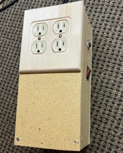
I made a power strip that has 4 independently switchable outlets from a raspberry pi and other materials that I mostly had sitting around. The raspberry pi is running Homebridge which turns it into a hub for Apple's HomeKit. This allows you to make the outlets switchable from your Apple devices and it enables you to leverage all the automations available in HomeKit as well.
The possible use cases are large. You could use this for many things such as turning lights and fans off and on when someone enters a room, or scheduling lights and pumps for fishtanks, or scheduling devices to turn on and off for taking care of plants.
The fact that it is running HomeBridge makes it not just a HomeKit enabled power strip, but it is also a hub you can use to connect many non-HomeKit enabled devices and make them visible to all of your Apple devices.
There are many instructables for creating smart power strips, but this one is a little different. I am using software that has a vibrant support community, so this methodology should work for a long time. The plug-in I chose to use to control the outlets with the raspberry pi has also been widely tested and is actively supported by its creator. In fact, I contacted him on Discord with some questions and heard back from him in a couple hours. However, there was so much support on GitHub and Discord that I had already found the answer to my questions.
PLEASE READ:
This project is potentially dangerous. Please do not attempt unless you know how to safely work with potentially dangerous voltages and understand how circuits work. I am not responsible for any problems that occur if you attempt this project. Proceed at your own risk.
Supplies
Almost everything I used to make the box can be substituted with different materials. I used wood because I had a board lying around and being a non-conductor I could attach the relays and raspberry pi directly to it without shorting out the contacts.
Used to make the box:
- a 12″x18″ piece of dense particle board
- #6 x 1-1/4″ wood screws
- smaller wood screws for securing the relay and raspberry pi to the board
- a double outlet cover
- drill with various drill bits
- table saw
- coping saw
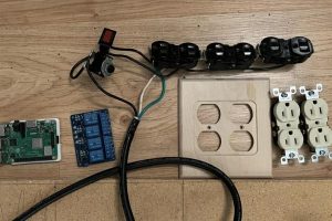
Used for the circuit and electronics:
- a board with 4 relays rated for 10A 125VAC that runs on 5V (3.3V could work too)
- a raspberry pi 3b+ (any raspberry pi that can run Homebridge will work)
- a power cord (taken from an old disassembled power strip)
- electrical wire used to wire homes
- female-female jumper cables
- (optional) a switch (taken from an old disassembled power strip)
- (optional) a surge protector (taken from an old disassembled power strip)
- various sized standard wire connectors
- wire strippers
- a small Philips head screw driver
- 2 standard home outlets
- an adjustable cable gland (I used a PG11 that is adjustable from 5mm-10mm)
- crimp-able insulated female disconnects
- a few feet of standard 2-wire electrical cables used in homes
- multi meter for testing
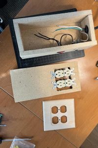
Step 1: Build a Box
Step 2: Set Up Raspberry Pi
To set up the raspberry pi you want to go here and follow the instructions for installing Homebridge:
https://github.com/homebridge/homebridge-raspbian-image/wiki/Getting-Started
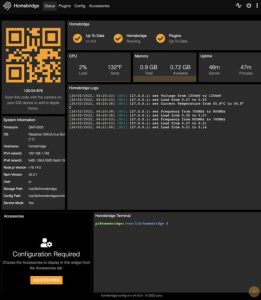
There are multiple ways to do it. I used the Raspberry Pi Imager and then followed the directions on the same page to connect the Raspberry Pi to my network. You can access Homebridge by going to any browser on your network and typing “http://homebridge.local”. There are instructions for connecting to HomeKit at the above link as well. It's a very simple process. Once you complete it, any devices you add to Homebridge through the Raspberry Pi will automatically show up in the Home app on all of your Apple devices.
After this you want to login into Homebridge, click on Plugins along the top, search for “Homebridge RPi” and install it. Once installed, you'll see a settings button on the “Homebridge RPi” plugin. Clicking on this will bring up a window with a form you can use to update the Homebridge config file. I included screen shots of the settings I'm using. You may need to use different GPIO numbers unless you wire the relays and Raspberry Pi together the same way I do. You just have to change the GPIO numbers to the ones you used. Please note the number the plugin needs to work properly is the number of the GPIO not the pin number. For example, pin number 3 in the included GPIO pinout diagram is GPIO2. If you wanted to use this pin, you would enter the number 2, not 3.
Raspberry Pi 3B+ Pinout Diagram:
https://www.jameco.com/Jameco/workshop/circuitnotes/raspberry_pi_circuit_note_fig2a.jpg
Warning: After finishing this project I got the scare of my life. While at work I received a notification on my phone, through the Home app, consisting of “Smoke Detected”. After panicking, I got a neighbor to check on it and unplug it. There was no smoke or anything obviously wrong with it. After some research, I found this warning occurs when the Raspberry Pi goes above 60°C. Which is not hot enough by far to cause a fire. To get rid of this I checked the “No Smoke Sensor” setting on Homebridge RPi. I've since left it plugged in for a long time and while it heats up, throttling lowers the temperature, and there seems to be no cause for concern that I can see. You may want to include heat sinks or add ventilation if you think you'll need it.
You may need to update some of the software on the Raspberry Pi in order for everything to work as expected. If you see any warnings generated in the logs on the Status page of the Homebridge about the versions being old you can update accordingly. There is a terminal built into Homebridge so you can easily do this.
Finally, you need to configure the pigpiod service. It is not set to start up automatically when the Raspberry Pi loads. Initially I followed the instructions for the “Local Raspberry Pi Configuration” which you can find at the link below. This did not end up working as expected. After some research and contacting the author of the plugin I found out what the problem was and that the solution was setting up the “Remote Raspberry Pi Configuration” which can be found at the same link. You may want to do that right from the start.
https://github.com/ebaauw/homebridge-rpi#readme
Step 3: Wire Raspberry Pi and Relays and Test
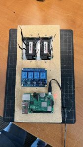
This step is fairly easy. First I located where I wanted to place the Raspberry Pi and Relays and I secured them using small wood screws. I then used female-female jumper wires to connect the Raspberry Pi and Relays. I connected one of the 5V pins on the Raspberry Pi to VCC on the Relays. Then connect one of the grounds on the Raspberry Pi to the ground on the Relays. Then connect the pins you want to use to control the relays. I connected it as follows:
GPIO26 to IN1 on Relay
GPIO19 to IN2 on Relay
GPIO13 to IN3 on Relay
GPIO6 to IN4 on Relay
The GPIO numbers should match the ones used in step two.
Now it is time to test the connections to make sure everything is working. If you did everything correctly you should now be able to turn the Relays on and off from your phone. You'll hear an audible click and the corresponding LED on the Relay board will turn on and off as you hit the switches.
Step 4: Wire Outlets to Relays and Power and Test
Here is where you will wire the relays to the outlets. First you have to prepare the outlets to make each outlet receptical in order for each outlet to be on an independent circuit. You do this by breaking the tab in the picture above with needle nose pliers. You should only break the tab on the hot side of the outlets. This is the side with the brass screws. Leave the tab on the side with the silver screws. Prepare the each outlet by attaching about 6″ lengths of wire to the terminals. Attach bare wire to the ground screws on each terminal. Attach black wires to each screw on the hot side of the outlet, the side with brass screws. Attach one white wire to the side with the silver screws.
The 4 black wires from the outlet will be connected to 1 Relay each. You have to choice of connecting it to the Normally Open (NO) terminal or the Normally Closed (NC) terminal. The difference is important for the behavior you want when the Raspberry Pi is not active. If you want the outlets to be off while the Raspberry Pi boots, choose NO, otherwise choose NC.
The white wires from the outlets should be connected to the white wire from the power cord. The ground wires from the outlet should be connected to the ground wire from the power cord. Use the appropriate standard wire connectors for both.
The black wire from the power cord should connect to the input of the surge protector. If you are not using a surge protector connect it to the power terminal on the switch. The output of the surge protector should connect to the power terminal on the switch. You should connect a black wire to the accessories terminal of the switch. Join four roughly 6″ lengths of black wire to this wire with an appropriate wire connector. Connect the end of the four black wires to the inputs of each of the four relays. If your switch has a third terminal it probably gets connected to ground. This is only to power the LED inside the switch so it lights up.
Make sure you do not leave any of the black or white wire exposed to avoid potential shorts and other hazards. Use the insulated crimp-able disconnects whoever possible to join terminals and wires easily and safely.
At this point I used a multi-meter to test for continuity and shorts everywhere in the circuit to confirm it was working as expected. Confirm that the relays do in fact open and close the circuit. I also made sure the switch worked. All the testing went as expected, so I plugged it in and found it worked correctly.
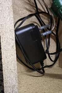
Step 5: Power Raspberry Pi Internally
Step 6: Finishing Touches, Final Thoughts, Things to Improve
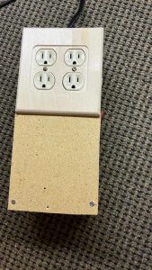
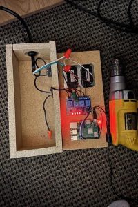
At this point I unplugged the device from power and carefully folded all the wires so that they would fit neatly in the box. I did my best to keep them neat to reduce the risk of shorts, inspecting to make sure that the bare parts of all the white and black wires were covered and couldn't come into contact with anything else. I then drilled holes on the corners of the top to complete the box to seal everything inside with the 1-1/4” wood screws. Finally I added the outlet cover.
I used wood for the enclosure because it doesn't conduct electricity. However, it also doesn't conduct heat well either. I may add some vents to it to improve cooling. Although, after having it plugged in for a long time the Raspberry Pi's normal operation of throttling to reduce temperature appears to work fine. The throttling doesn't seem to impact performance at all. If you connect additional devices to the Raspberry Pi to make them accessible via HomeKit you may find that it heats up too much or that throttling causes issues. Heat sinks on the Raspberry Pi might help, or a small exhaust fan could be added as well.
The enclosure is much bigger than necessary. I built this quickly as a rough draft or proof of concept and I wanted plenty of room for the electronics and wires. It can be made much more compact, and could be prettier.
There are many plugins available on Homebridge that are designed to connect non HomeKit smart devices and make them HomeKit compatible. I plan to see if I can do this with my garage door opener.