
This tutorial shows you how to connect Raspberry Pi to CAN Bus (e.g. your car), explaining the role of each part and some recurrent errors.
This post was originally published on my blog: http://youness.net/raspberry-pi/raspberry-pi-can-bus.
In this post, I will explain you how to connect Raspberry Pi to a CAN Bus (e.g. your car).
Firstly, know that Raspberry Pi boards aren't ready out-of-the-box for CAN.
Bus. are +50 Google Search pages about this topic, we can sum up them in two points:
- CAN Bus isn't supported by Raspberry Pi hardware (GPIO).
- CAN Bus isn't wasn't supported by Raspberry Pi software (Raspbian).
TL;DR:
- We will use a bridge between Raspberry Pi and CAN Bus: SPI Bus.
- We will use a CAN controller supported by Linux/Raspbian: MCP2515.
That means that the below instructions are tested “mainly” for MCP251x family.
It's a widely used component, I may add more CAN controllers in the future.
That said, the theory remains the same for any component that you are using.
If you have any question or remark, I'll be happy to help you, feel free to leave a comment.
1. Hardware
1.1 CAN Bus Basics
1.1.1 CAN Wiring
CAN Bus uses two-wires differential signals.
One is called CAN-H (High) and the other CAN-L (Low).
1.1.2 CAN Node
CAN Bus needs at least two nodes to make the network “up”.
So testing with one node will not work: this is the mistake n°1: Never use only one CAN Bus node.
1.1.3 CAN Termination
CAN Bus needs termination resistors between CAN-H and CAN-L at each end.
Mainly to avoid signal reflections. ISO 11898 recommends the value R=120Ω.
And that's the mistake n°2: Without termination your CAN Bus will not work correctly.
1.1.4 CAN Controller
CAN Bus is a multi-master protocol, each node needs a controller to manage its data.
CAN controller is connected to the CAN bus using CAN-H and CAN-L.Example of controllers: MCP2515, SJA100,…
1.1.5 CAN Transceiver
CAN controller needs a send/receive chip to adapt signals to CAN Bus levels.
Controller and Transceiver are connected by two wires TxD and RxD.
Examples: MCP2551, TJA1040…
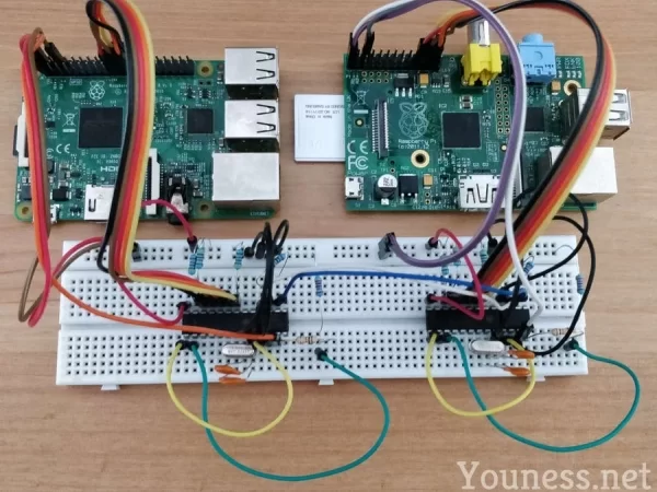
Regrouping all the above parts:
I'll hide the node B for the rest of the post.
1.2 SPI Bus Basics
1.2.1 Why SPI?
Raspberry Pi doesn't have a built-in CAN Bus (that's why we are doing all that…)
But its GPIO includes SPI Bus, that is supported by large number of CAN controllers.
SPI Wiring
SPI Bus uses 4 connections as follow:
- MOSI (Master Out Slave In)
- MISO (Master In Slave Out)
- SCLK (Serial Clock)
Adding to that two other pinouts:
- CS or SS (Chip Select, Slave Select) to enable and disable the chip.
- INT (Interruption) to interrupt the chip when needed.
For that project you don't really need to know more than that about SPI connections.
Including Raspberry Pi to the previous schematic gives:
Let's move now to some practical details.
1.3 Components
1.3.1 MCP2515 (CAN Controller)
Supply:
The MCP2515 can work at 5V or 3V3, so it can be connected to Raspberry Pi GPIO.
Clock:
The MCP2515 needs an external quartz.For a value of 16Mhz, the datasheet recommends two capacitors of 22pF each.
Pull-up:
Three pins need a pull-up resistor to stay at a recognized level, I took 4K7 (4,7KΩ) resistors. The pins are:
- Pin 17 for Reset.
- Pin 16 for CS.
- Pin 12 for INT.
The SPI bus itself (MOSI, MISO, SCLK) doesn't need pull-up resistors.
1.3.2 MCP2551 (CAN Transceiver)
Supply:
Contrary to the MCP2515, the MCP2551 can only work at 5V.
That is the mistake n°3: Incorrect voltage levels between IC and Raspberry Pi.
If you connect MCP2515 to MCP2551 directy, the signals will not have the same level.
The 5V-to-3V3 can be done in several ways, as explained for example in this Microchip 3V Tips ‘n Tricks. (see below)
Reset:We will not need to reset the MCP2551 so the pin 8 can be connected to GND.
1.3.3 5V to 3V3
The easiest way for me is by a resistor divider (voltage divider) between MCP2515 and MCP2551.
We need this divider only for the RxD since here where the 5V will come in.
I used two resistors:
- R1: 10K (10KΩ)
- R2 = 22K (22KΩ)
You can use different values as far as the result is the same with an acceptable current/voltage.
1.4 Overall schematic
I put the pinout numbers, not the GPIO numbers, I think that it is easier to follow.
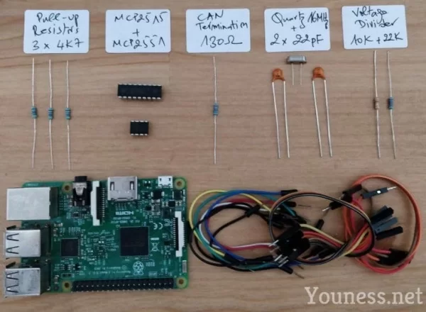
1.5 Bill of Material
2. Software
I'm using Raspbian, and I like to start all the time with a fresh and updated version.I'm using Raspbian Stretch lite, since we don't really need a desktop environment.
Update/Upgrade and reboot:
sudo apt-get updatesudo apt-get upgradesudo rebootUsual customizations: Wi-Fi, keyboard, SSH…etc.
If you need specific help for all that, please leave a comment.
2.1 Why MCP251x?
Until some time ago, most of CAN by SPI controllers weren't supported out-of-the-box by Linux kernels. It was mandatory to compile by yourself the modules and attach them, and this has to be done after every major system update. If you are interested by this part of history, you can read my 2015 post here.
Today things are much easier, Linux kernels added support for MCP251x (and other controllers), so you can directly load them like any other hardware peripheral.
2.2 SPI/CAN Configuration
Enable SPI and overlay it as follows:
sudo nano /boot/config.txtUncomment the line:
dtparam=spi=onAfter the above line add this:
dtoverlay=mcp2515-can0,oscillator=16000000,interrupt=25dtoverlay=spi0-hw-csThe above lines to overlay SPI and set can0 interface to 16MHz, and interruption to GPIO25 pin.
This is the correct way for +4.4.x kernels, the mistake n°4 is to use a deprecated overlay method. (For earlier versions the overlay may be different)
Save the file: CTRL+X, then Y, then Enter.
Reboot, you can check that the SPI module was started:
dmesg | grep -i spiBy the same command you can check the CAN module is started by default:
dmesg | grep -i canIf for any reason this is not the case, you can add CAN module at system start:
sudo nano /etc/modulesAdd “can” in a new line, save the file and reboot.