
How to interface servo motor with Raspberry pi
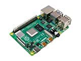
In this project, we will Know about How to interface servo motor with Raspberry pi For this project, we will be using the Raspberry Pi 4 and Tower Pro MG995 Servo Motor. Below is a list of all the components you need to complete this project Components Required 1. Raspberry Pi
2. Tower Pro MG995 Servo Motor
4. Power Supply
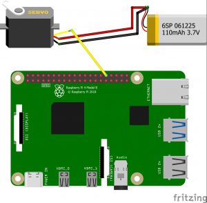
This book will help you to know more about raspberry pi 20 Easy Raspberry Pi Projects For this project, you have to need to know a technics PWM, In the PWM technique, you will be sending a pulse of variable width and the position of the Servo Motor’s shaft will be set by the width or length of the Pulse. The frequency of the PWM signal is a fixed value and is dependent on the type of Servo Motor. For this project, MG995 Servo Motors have a PWM frequency of 50Hz. For know more about This servo MG995 reed Datasheet in this link At 50Hz i.e. a period of 20ms, the minimum pulse width is 1ms and the maximum pulse width is 2ms. Most servo motors can have a swept area of 180 degrees i.e. 90 degrees on either side of the neutral position Raspberry pi PWM Servo(MG995) Interfacing with Raspberry pi PIR Raspberry pi4_SERVO In this project, we used raspberry pi4 and raspberry pi4 all pin is not PWM Pin only 4 are PWM pin But I have connected the PWM pin of Servo with Physical Pin 22 of Raspberry Pi4 Connect the VCC and GND of the MG995 Servo Motor to +5V and GND pins of the power supply. Then connect the PWM Pin of the Servo Motor to Physical Pin 22 of Raspberry.
Make the ground common between Raspberry Pi and the Power Supply of the Servo Motor
Servo Motor Control Python Code
Rotating 180 degrees in 10 steps

Loop to allow user to set servo angle
Raspberry Pi Project: PIR Motion Sensor using Raspberry Pi4 | Interfacing Tutorial PIR Sensor -Email Sending Movement Detector using IFTTT Controlling a DC Motor with Raspberry Pi4 How to Use the Raspberry Pi4 Camera And PIR Sensor to Send Emails Raspberry Pi Distance Sensor using the JSN-SR04T How to connect 16×2 LCD with Raspberry pi How to interface RFID-RC522 with Raspberry Pi
Schematics
Code
| # Import libraries | |
| import RPi.GPIO as GPIO | |
| import time | |
| # Set GPIO numbering mode | |
| GPIO.setmode(GPIO.BOARD) | |
| # Set pin 11 as an output, and set servo1 as pin 11 as PWM | |
| GPIO.setup(32,GPIO.OUT) | |
| servo1 = GPIO.PWM(32,50) # Note 11 is pin, 50 = 50Hz pulse | |
| #start PWM running, but with value of 0 (pulse off) | |
| servo1.start(0) | |
| print (“Waiting for 2 seconds”) | |
| time.sleep(2) | |
| #Let's move the servo! | |
| print (“Rotating 180 degrees in 10 steps”) | |
| # Define variable duty | |
| duty = 2 | |
| # Loop for duty values from 2 to 12 (0 to 180 degrees) | |
| while duty <= 12: | |
| servo1.ChangeDutyCycle(duty) | |
| time.sleep(1) | |
| duty = duty + 1 | |
| # Wait a couple of seconds | |
| time.sleep(2) | |
| # Turn back to 90 degrees | |
| print (“Turning back to 90 degrees for 2 seconds”) | |
| servo1.ChangeDutyCycle(7) | |
| time.sleep(2) | |
| #turn back to 0 degrees | |
| print (“Turning back to 0 degrees”) | |
| servo1.ChangeDutyCycle(2) | |
| time.sleep(0.5) | |
| servo1.ChangeDutyCycle(0) | |
| #Clean things up at the end | |
| servo1.stop() | |
| GPIO.cleanup() | |
| print (“Servo STPO”) |