
Whether you can't afford a USB controller, or you just want the the challenge, making your own retro game controller is a great idea!
This controller will use the GPIO pins on the Raspberry Pi, so you will need some experience working with electronics. Otherwise, you might fry your Pi. Also, this is an excellent way of learning how to work with the Pi's GPIO pins.
We will use the GPIOnext software to interface the custom controller to your Pi.
Also, I will simply mount buttons to a breadboard, but if you want to make it ergonomic, and not be open, you can solder buttons to a board and 3d print a case for it. I won't.
Also, you can use this to make a arcade system, with pushbuttons and a joystick.
Supplies
Here are the supplies you need. I won't cover the materials you need to 3d print a custom case:
Raspberry Pi: I hope you have one! I used a Pi 4b
Breadboard: Use this to make/prototype your controller.
Wire of some sort: I used jumper wires, but you can use the wires that stick to the breadboard. Take lots.
Buttons: Get buttons that you can wire to your breadboard. I used 10 tactile buttons
Digital Joystick(optional): You must use one that has digital output, like this: https://www.adafruit.com/product/480
Analog ones(with pins +5v, GND, Vrx Vry, Sw) won't work.
Female to Female jumper wires: Use these if you do not have a GPIO breakout board, or you use a digital joystick
Raspberry Pi GPIO Breakout: This is optional, but I find it easier to work with one.
Internet Connection
USB Keyboard
Step 1: Prepping Your Pi
There are some stuff we have to do before making the controller.
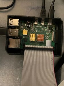
First, open up your case for your Pi if you have one, and boot the Pi up. You should also find what version it is in the mean time.
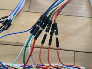
Then, plug in your ribbon cable for the GPIO breakout board, according to the instructions they gave you. If you do not have one, grab your FtoF(female to female jumper) cables, but hold up until the next step.
Step 2: Choosing Your GPIO Pins
When wiring the buttons to your pi, you will need to choose the GPIO pins you will use. The basic buttons you need is four buttons for a D-Pad or one digital joystick, 4 buttons for a/b/x/y and 2 for start and select. I used 10 buttons/inputs, so I need 11 GPIO pins. Why? You also need one for the negative terminal If you use a digital joystick, add 4 inputs to your other inputs. If you want to copy mine, there is a diagram later on.
With your inputs, check out the the diagram at https://learn.sparkfun.com/tutorials/raspberry-gpio/gpio-pinout. Note: This diagram is meant for the pi 2 and onward. Find the green pins. These are all the pins you can use. Choose your pins, and take note of the pin number, on the side. You might need these later on.
Non-breakout board users:
After choosing your GPIO pins, refer to both the image above and the GPIO diagram to plug in your FtoF cables. Plug in each cable to the correct pins. It is crucial that you plug in your wires in the right port. You should now have the wires connected. With that, onto the next step!
Step 3: Build/Prototype Your Controller
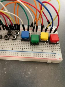
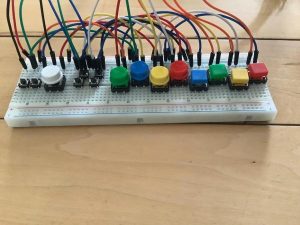
Now, put the buttons in to the breadboard. Make sure that you connect them, like above, pushed all the way down. Notice how on each button two of the pins, connected at the short side are on the side on the top? This is crucial to make it less messy. Reference to my controller, at the top, to copy my layout Now, on each button, find the pin to the right, on the top half, and connect it to the negative terminal, like above.
If you used a digital joystick, find the GND pin. Take a wire and plug in the GND pin to the negative terminal.
Step 4: Wiring Your Controller: Breakout Method
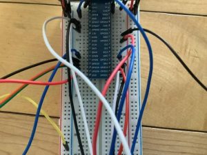
Back to the other board. I used a breakout board, which I find easier to work with. Grab jumper wires, and plug in one to the left pin of each button, in my image above. Then, take the other end and plug it into GPIO inputs on the board. If you have a digital joystick, take a wire from each pin, then plug it in to a GPIO pin. That's it!
Step 5: Wiring Your Controller: FtoF Cable Method
Find the cable connected to GND. Take a jumper wire, and plug in one end to the GND FtoF cable, then other side to the negative terminal. Alternatively, you can use a male to female jumper wire. The other button cables can be connected to the other cable. That's it!
Step 6: Software Setup
There is some software we need for this controller to work. We need GPIOnext, pip3, and evdev. The commands you need to run are below, in the text file. Open up the terminal in RetroPie with f4. Run the commands below. The first command updates your pi, the next few install evdev, and the last few install GPIOnext. If there is any error, search it up online! You'll be surprised how much you can learn by just searching it up.
sudo apt-get update && sudo apt-get full-upgrade -y
sudo apt-get install python3-pip
sudo pip3 install evdev
cd ~
git clone https://github.com/mholgatem/GPIOnext.git
bash GPIOnext/install.sh
Step 7: GPIOnext Setup
When the last command is run, you will have the option to run GPIOnext config. Type y. If you didn't, don't worry. Just type the text below in the terminal. Ignore the quotation marks. If all goes well, with words Joypad 1, and so on, skip the next step. If it did not work, read on.
gpionext config
Step 8: GPIOnext Debugging
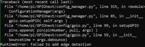
You probably go the error above. If not, check online, and if you can't find anything, post your issue here: https://github.com/mholgatem/GPIOnext/issues, the official Github page.
Now, to fix this, you need to get the pin numbers the inputs are connected to. You need the numbers on the side, from the diagram in 2. I used the pins 22, 31, 32, 33, 35, 36, 37, 38, 39, 40. So, you need to run the command below, replacing the numbers to the pins you use. You can also type every number from 1 to 40, but that is not necessary.
sudo python3 /home/pi/GPIOnext/config_manager.py --pins 22,31,32,33,35,36,37,38,39,40
Then type the commands below, again replacing the numbers to the pins you used
gpionext set pins 22,31,32,33,35,36,37,38,38,39,40
gpionext reload
Step 9: Configure Your Controller
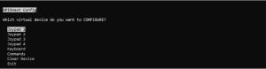
If all goes correct, you should get a image like above. Hit enter selecting joypad 1, then fill in your data. I used 1 d-pad, a start, select, and a/b/x/y buttons. Make sure you use spacebar on the button selections. After that, it asks you to press the buttons you used. It will save and finish.
Type the text below to start your controller
gpionext start
Step 10: Playing Games
Like any other controller, you need to configure this one. Go to that configure menu in Retropie by clicking START, then CONFIGURE INPUT. If you have no configured device, then a screen will show up to configure your controller.