
What Are The GPIO Pins on Raspberry Pi?
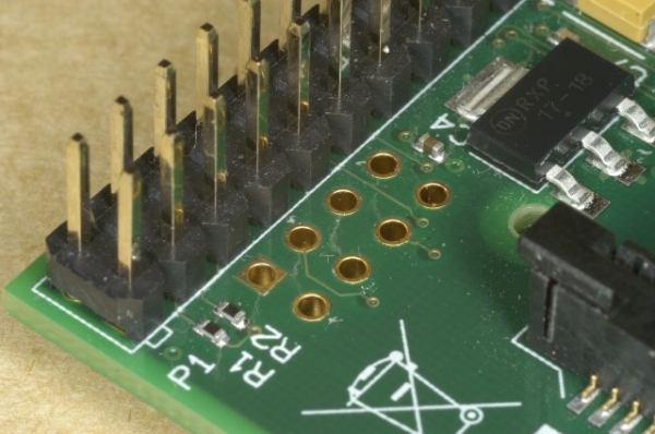
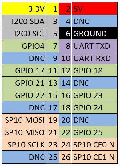
A great feature on the Raspberry Pi is the GPIO pins (stands for General Purpose Input Output). These GPIO pins on Raspberry Pi can be found in 2×13 header pins which can perform tasks include SPI, I2C, serial UART, 3V3 and 5V power.
There are eight of these pins can be used directly for digital output and input (Hight and Low). These pins can be set high by connecting it to a voltage supply, or set low by connecting it to ground.
So you can control electronics devices such as LEDs, Motor Driver and so on using these GPIO pins. Input devices like push buttons and toggle switches can also be used to control the Raspberry Pi.
How To Control and Use GPIO Pins on Raspberry Pi?
This includes two steps, software on the Pi, and how to connect the hardware.
Install RPi.GPIO Python Library
The RPi.GPIO Python Library probably have come pre-installed on your Raspbian OS, to verify this, fire up Python:
sudo python
and type in this line
import RPi.GPIO as GPIO
If you don’t get any error, you are should be fine. If you do get an error, then do the following to install the library.
To install it launch a command line (i.e. LXTerminal) and enter the following commands :
- Download the RPi GPIO Library
wget http://pypi.python.org/packages/source/R/RPi.GPIO/RPi.GPIO-0.3.1a.tar.gz
- Extract the files
tar zxf RPi.GPIO-0.3.1a.tar.gz
- Browse to the extracted folder
cd RPi.GPIO-0.3.1a
- Install the library
sudo python setup.py install
The Library should be ready now.
Usage of the Python RPi.GPIO Library
[sourcecode language=”python”]
# import library
import RPi.GPIO as GPIO
# to use Raspberry Pi board pin numbers
GPIO.setmode(GPIO.BOARD) # or GPIO.setmode(GPIO.BCM)
# set up the GPIO Pins – for input or output
GPIO.setup(11, GPIO.IN)
GPIO.setup(13, GPIO.OUT)
# taking input value from Pin 11
input_value = GPIO.input(11)
# setting output value to Pin 13
GPIO.output(13, GPIO.HIGH)
#GPIO.output(13, GPIO.LOW)
[/sourcecode]
 The difference between GPIO.setmode(GPIO.BOARD) and GPIO.setmode(GPIO.BCM) is the pin numbering system. BOARD signifies using the physical pin numbers on the Raspberry Pi P1 connector. BCM signifies the Broadcom SOC channel designation. However you should know the BCM channels changed a little between revision 1 and revision 2 of the Raspberry Pi board, and the BOARD numbering system stays working between board revisions.
There are 8 available GPIO Pins on Raspberry Pi.
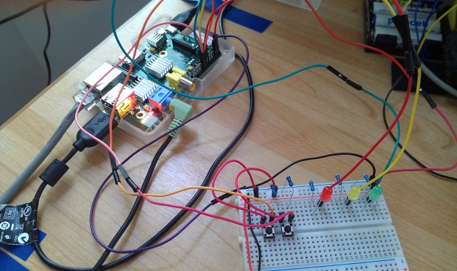
Resistors value can be caculated as this. My 5mm LED’s forward current is around 20mA (might be different to yours), voltage supply from RPi is 3.3V, so the resistor for LED is 3.3 V / 20 mA = 165 omh. For the push buttons, I used 1K ohm resistors.
Source Code
[sourcecode language=”python”]
from time import sleep
import RPi.GPIO as GPIO
GPIO.setmode(GPIO.BOARD)
GPIO.setup(16, GPIO.IN)
GPIO.setup(18, GPIO.IN)
GPIO.setup(11, GPIO.OUT)
GPIO.setup(13, GPIO.OUT)
GPIO.setup(15, GPIO.OUT)
GPIO.output(11, GPIO.LOW)
GPIO.output(13, GPIO.LOW)
GPIO.output(15, GPIO.LOW)
# state – decides what LED should be on and off
state = 0
# increment – the direction of states
inc = 1
while True:
# state toggle button is pressed
if ( GPIO.input(16) == True ):
if (inc == 1):
state = state + 1;
else:
state = state – 1;
# reached the max state, time to go back (decrement)
if (state == 3):
inc = 0
# reached the min state, go back up (increment)
elif (state == 0):
inc = 1
if (state == 1):
GPIO.output(11, GPIO.HIGH)
GPIO.output(13, GPIO.LOW)
GPIO.output(15, GPIO.LOW)
elif (state == 2):
GPIO.output(11, GPIO.HIGH)
GPIO.output(13, GPIO.HIGH)
GPIO.output(15, GPIO.LOW)
elif (state == 3):
GPIO.output(11, GPIO.HIGH)
GPIO.output(13, GPIO.HIGH)
GPIO.output(15, GPIO.HIGH)
else:
GPIO.output(11, GPIO.LOW)
GPIO.output(13, GPIO.LOW)
GPIO.output(15, GPIO.LOW)
print(“pressed B1 “, state)
# reset button is pressed
if ( GPIO.input(18) == True ):
state = 0
inc = 1
GPIO.output(11, GPIO.LOW)
GPIO.output(13, GPIO.LOW)
GPIO.output(15, GPIO.LOW)
print(“pressed B2 “, state)
sleep(0.2);
[/sourcecode]
Conclusion
Although the Raspberry Pi has much more powerful computational capacity than the Arduino, it’s shortage in digital pins and analogue pins is still a disadvantage for many DIY, electronics hobbyists. However there are possibilities in expanding the number of digital pins and adding analogue pins. I might do some projects around these area in the near future.
Source: How To Use GPIO Pins On Raspberry Pi – Buttons And LED Tutorial