
I. Introduction
FOR the 2017 solar eclipse ballooning, the live streaming of the videos capturing the shadows of the solar eclipse was one of the main objectives. All teams who participated in the 2017 solar eclipse ballooning project were initially provided with a baseline ballooning system [1][2] that consisted of a ground station and four standard payloads for still image, video, Iridium-based tracking, and cut-down. In particular, the standard video payload for live streaming was primarily composed of a Raspberry Pi board with a Pi-camera module to capture high-definition video during balloon flight and a 5.8 GHz Ubiquiti Rocket M5 modem to transmit the video to its counterpart M5 modem on the ground station. The Pi-camera was installed on a servo motor to be able to adjust its viewing direction to some extent but its primary viewing angle was still toward only one of the four directions, i.e., north, south, east, and west of the payload position. To overcome this drawback and be able to capture video images from more than one direction, there were several approaches adopted by some other solar eclipse ballooning teams, such as placing the Pi-camera on a servo motor on top of the video payload, developing a video multiplexor board that could select one of the video streams from multiple Pi-cameras facing different directions, or replicating multiple Raspberry Pi boards, each with aPi-camera and a dedicated M5 modem to simultaneously transmit all live video streams from multiple Pi-cameras on multiple 5.8 GHz modem to the ground for further processing. Each of these approaches presents pros and cons in achieving the objective of capturing the solar eclipse images live from multiple viewing directions, but the analysis of such pros and cons is omitted herein as it falls beyond the scope of this paper.
Different from the approaches mentioned above, we have developed a video payload that can simultaneously livestream multiple videos via a single 5.8 GHz wireless link. The key design aspects we explored and ultimately adopted were 1) using more than one camera on a Raspberry Pi board and 2) multiplexing all video streams from multiple cameras onto a single stream of data traffic that a single 5.8 GHz radio modem can transmit to the ground station. With much troubleshooting and careful optimization of all components’ functionality for this method, we have finally chosen to use 4 Raspberry Pi’s, each with an SD memory card and two cameras (a Pi-camera and a webcam), and a high-bit-rate network switch, as well as a power-over-Ethernet (POE) device and an M5 AirMax modem transmitting through two rubber-duck antennas as originally included in the standard video payload. As our design objective for the video payload was to cover four non-overlapping directions of north, south, east, and west from the payload orientation, only four of those eight cameras were used for live streaming while all video streams from the eight cameras were stored on the on-board memory cards. In this paper, we present technical details of our video payload implementation. Section II presents an overview of the system. In Section III, technical details of simultaneously operating two cameras on a single Raspberry Pi is first provided. Then, as one of the key aspects of our approach, we describe how multiplexing of multiple video streams into a single data stream was achieved such that a single M5 modem could transport all video streams to the ground station through the 5.8 GHz link. Various key factors are also discussed in optimizing the wireless transmission from the M5 modem on the video payload while ensuring acceptable quality of the live video at the ground station.
II. Overview of the System
An overall functional block diagram of our video payload is shown in Fig. 1 along with its counterpart in the
ground station. As shown in the diagram, on the payload side, each of the four Raspberry Pi’s is assigned a static IP address sequentially from 105 to 108, i.e., 192.168.1.x, and integrates one webcam and one Pi-camera. The webcam is connected to one of the four USB ports of the Raspberry Pi and the Pi-camera was connected to the Pi-camera serial interface slot available on the Raspberry Pi (version 2, Model B). For data communication, each Raspberry Pi is connected to an Ethernet switch via a category-6 flat Internet network cable with RJ45 connectors on both ends.
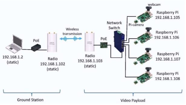
The Ethernet switch facilitates data flow between the radio modem with a static IP address (e.g., 192.168.1.103)
and four Raspberry Pi’s. The Ethernet switch we have chosen supports five 10/100/1000 Base-T Ethernet ports and thus each port is compatible with the 10/100 Base-T Ethernet port available on the Raspberry Pi board. Four Ethernet ports are used for data flow to/from four Raspberry Pi’s, respectively, and the 5th Ethernet port is for data flow to/from the Power-over-Ethernet (PoE) board which was a part of the standard video payload initially provided to us. As the Ethernet switch must be able to function properly over a wide range of temperatures for the high-altitude ballooning purposes, we have chosen an industrial Ethernet switch that can operate in a temperature range of -40° to 167°F (-40° to 75°C). Note that typical commercial Ethernet switches operate in a narrower temperature range such as 32° to 122°F (0° to 50°C). There are other industrial Ethernet switches that support up to 8 Ethernet ports which could in turn facilitate data flow between the radio modem and up to 8 Raspberry Pi’s. Also, in principle, more than one Ethernet switches could be connected in a cascade to facilitate data from to/from any number of Raspberry Pi’s. However, considering various factors that are identified in the following section, we had finalized our video payload with four Raspberry Pi’s and thus a single five-port Ether switch was a suitable choice.
The radio modem is a 5.8 GHz Ubiquiti modem, the Rocket M5, as included in the standard video payload and
paired with a PoE device shown in the block diagram. Our troubleshooting and configuration to optimize the operation of the M5 modem to support simultaneous live streaming of videos from four Raspberry Pi’s is further described in the following section. On the ground station, another pair of an M5 modem and a PoE device is used as installed on the ground station system. The configuration of the M5 on the ground station is required to match in most parameters except for one. We will discuss this further as well in the next section. Then, the PoE is connected to a laptop computer on which a software application to display four streaming videos is run. We have used both VLC media player and Open Broadcaster Software (OBS). Note that the VLC supports a single stream display on a pop-up window and thus
multiple VLC pop-up windows are necessary for simultaneous multiple streaming. The OBS can be configured to display multiple streaming videos on a single pop-up window and thus, it was our choice to upstream simultaneously four live-streaming videos from our video payload on to the on-line repository site during the August 21, 2017 solar eclipse ballooning.
III. Details of Subsystem Configuration
A. Video Streaming with Two Cameras on a Single Raspberry Pi
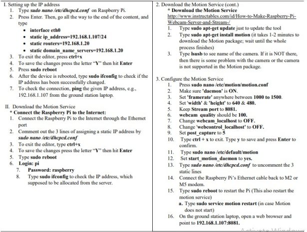
For the integration of multiple cameras on to the Raspberry Pi, the design requirement we initially set was to keep the Pi-camera as is on the Raspberry Pi board, as given in the standard video payload [2], but add more cameras. As there is only one Pi-camera slot on a Raspberry Pi, this requirement led to using an additional webcam through one of the four USB ports available on the Raspberry Pi. To establish the video streaming capability with a Pi-camera on a new Raspberry Pi for exploration and testing, we first replicated another Raspberry Pi using the configuration from the image file distributed during the July 2016 workshop organized by the Eclipse Ballooning Project team
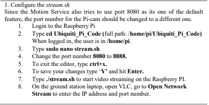
[3].One of the challenges was the encoding and processing of multiple video streams in the Raspberry Pi mainly due to the large amount of data for video streaming. The H.264 encoder was used to compress and process the video from the Pi camera as this encoding scheme can deliver high-definition video at a reduced data rate. For the webcam video, we adopted the commonly used, Motion-JPEG (MJPEG) scheme to encode and process the video as it was relatively simpler to set up compared to the H.264 encoding. The steps shown in Fig. 2 and Fig. 3 were taken to establish video streaming with two cameras. Note that, for the radio modem in this development, we utilized an M2 modem, which is from the same vendor and has the same functionality as the M5 except that it operates on the 2.5 GHz band. Both M2 and M5 are configured by the same software, airOS [4]
While two sources of video streaming were available on each Raspberry Pi, we have chosen to stream only one
from the Pi-camera primarily due to the limited transmission capacity of the radio modem and also the amount of data required for video streaming from the two sources of video, which are two of the key factors for the quality of the video received and displayed at the ground station. We observed that, for the video streaming, the central processing unit (CPU) on the Raspberry Pi re-directs the raw video input from the Pi-camera to its Dual VideoCore IV® Multimedia Co-Processor functioning as a graphics processing unit (GPU) and thus, is less CPU processing-intensive than the CPU processing required for the raw video input from the webcam. With the Pi-camera used for live streaming, the Raspberry Pi consumed only 6-8% of its CPU processing power and in turn was able to facilitate other processing better such as keeping the communication session between the Raspberry Pi (e.g., 192.168.1.105) on the video payload and the computer (i.e., 192.168.1.2) at the ground station. On the other hand, for the webcam, we have integrated a Microsoft LifeCam HD‑3000. Since the USB ports on the Raspberry Pi are not connected to the graphics processing unit, the processing of the encoding and transmission of the video is done by the CPU itself. We observed that general video recording and streaming consumed around 65 – 90% of the CPU processing power of the Raspberry Pi. This heavy use of the CPU processing power often resulted in a loss of communication session between the
Raspberry Pi and the computer at the ground station.
Source: Implementation of Simultaneous Multi-Streaming of Live Solar Eclipse Video via 5.8 GHz AirMax