
Hello DIY makers and coders…. Today I'm presenting my version of a custom Macropad with a Raspberry Pi Pico….
I named this as “Infinity Macropad 1.1″….the project is based on the adafruit Circuit Python and runs HID functionality onboard….
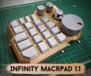
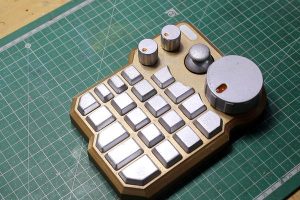
This Macropad has
- 20 individual tactile push buttons
- 3 Rotary encoders
- 1 Joystick
- 1 Ws2812b Status RGB LED
- Micro usb port
- Inclined kickstand
I want to make this project completely open source and share the whole setup with everyone free of cost… And for that purpose I need a good amount of help from people who are expert in circuit python programming… Pls help…
. So without wasting anyone time..lets get started…
Step 1: Understanding the Project and Chossing Right Microcontroller
I wanted to make a macropad.. Which will have enough buttons for almost every programs and applications…
Fow which I decided to include 20 buttons, 3 rotary encoder and a joystick… (these encoders and joystick also have their own push buttons…)
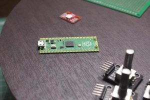
Now.. For making the project… The most powerful but compact microcontroller was the Raspberry Pi Pico…
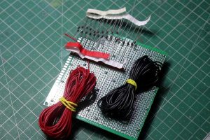
Step 2: The Parts We Are Gonna Need…
For making the project… We will need these parts.
Components
- 20 tactile switches…(12*12*12 switches)… I could have gone with cherry mx switches… But they are much pricer
- 3 rotary encoder modules
- 1 XY joystick module
- 1 ws2812b led module
- 20 4148 switching diodes
- Raspberry Pi Pico
- 10 * 10 cm zero pcb
- 5 screws (3mm thick)
- My 3d files or your own…
Tools
- 3d printer
- Fusion 360 or any other CAD software
- PLA or favorite plastic roll
- Spray paint (optional)
- Some random tools
Step 3: Preparation of the PCB…
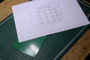
Firstly print my given template for the PCB board…
Cut it out and carefully allign with the board and stick it…
After that using the guide lines… Cut the PCB board… I used my small coping saw… You can use whatever available…
After the cutting is done.. Carefully place the switches in their places… And mark their location on the board…
Step 4: Adding the Push Buttons…
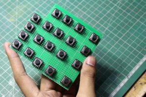
Now with the previously made markings… Place the switches in their corresponding places….
Make sure the placements are perfect.. Otherwise it will be very hard to rectify it later…
Double check their placements…
Now.. Bend 2 legs of the buttons and solder them on the board… You can solder all 4 legs.. But it will increase the confusion…
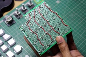
Step 5: Placing the Matrix Diodes…
We are making a 4*5 button matrix… And for that purpose… We also need some diodes…
You can use normal 4007 diodes… But everyone suggest to use 4148 switching diodes… So.. I'm going with them also…
The circuit would be look like this… 👇
Make sure of the polarities of the diodes and the directions of them…
In my project.. I places them in two orders… But the wiring is same… It's just to make them tidy…
Use thin copper wire.. I used 26 gauge wires.. And connected all the columns together..
Then the drain of the switches to the diode…
The output of the diodes together in series… To form 5 individual rows…
Use reference pictures for better understanding…
Step 6: Drill the Mounting Holes…
I did this step after the wiring is done.. Because I'm obviously a professional dumb…
You should do this step before the wiring….
I dodged the bullet in first chance due to my prior thinking and because it's my design.. But it might be devastating for you…
So don't make my mistakes…
I simply drilled the hole with 4 mm drill bit… And as always I messed up the holes… They were not in right spot..anf not perfect round… So I used my rotary tool with a tungsten carbide bit.. And fixed those issues…
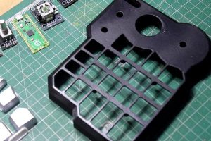
Step 7: Remove the Header Pins… and Paint the Case…
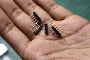
It's the time.. When you should remove the male headers from the rotary encoder modules and the joystick modules…
Also it's a good time to add wires to them… So you don't have to do them later…
After the wiring is done… It's time for painting the macropad body…
Though it's a optional step… You can directly print in your desired colour… But… I did it anyway…
Firstly I painted the body with spray paint.. And then finished with clear coats… (I later printed the main body again… Due to some design issue…so then I changes the colour.. From black to gold)…
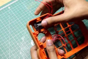
Step 8: Assembling the Parts…
- Firstly start the assembling with the led cover… It's designed to be just friction fit… But I later used some E7000 glue for better fixing…
- Add the rotary encoders… One thing I want to mention here… The rotary encoders have small notch type things… We need to either bend them flat… Or cut them off… Fix them with the provided washer and nuts…
- Now add the joystick module.. In it's place.. And secure with the 3 screw holes provided… I again used some E7000 for better fixing…
- Place the button matrix in it's place… And secure with the screws and some washers…
- Add the Raspberry Pi Pico.. And fix it with some E7000 glue… It's very important here.. Because.. Due to my design limitations… I done have space for mountaing it properly… Though… I have plenty support structures in many places… (find them out…)
One thing I want to say here.. That… You have to trim the excess solder joints from the modules and cover thm with glue… For makeing sure that nothing sorts with the Pi pico… And it sits flush…
Step 9: Reprint the Whole Main Body…
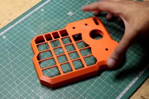
I made some boo boos…. In my designs… And also accidtly melted the previous body with slight tough of my soldring iron… So I had to print another piece…
Now… I painted it with gold paint… And it looks way better than previous one… I am telling you… This rustic gold colour is way beautiful than the previous black colour….
Step 10: Wiring Time…!!!
I again assembled every parts in their intended places again… And it's time for the wiring…
One thing you should notice before starting the wiring…
Pi Pico has many io pins.. And in those… Only 26 gpio pins are usable(still way much than arduino boards…)
Also… Pico has ground pins on every 5th pins… With square pads… So mind those one also…
…
Wiring time….
- I connected all coloums to the GP 0, GP1, GP2, GP3 pins…
- All rows to GP4, GP5, GP6, GP7 & GP8 pins…
- The first rotary encoder to GP9, GP10 & GP 11…
- Others two encoders to GP 12,13, 14,15,16 & 17…
- The joystick module to GP 18,19 & 20….
- And the Ws2812b led To GP21 pin…
*follow my wiring diagram…
Also all the grounds to ground pins… And the 5 volt pins to GP40 (Vbus) pin… (5.volt output pin)
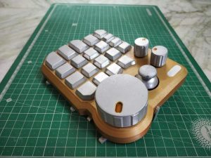
Step 11: Add the Knobs.. Closing the Project..
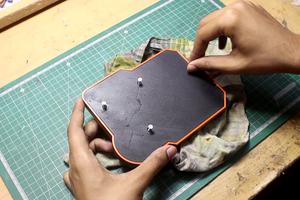
It's the best time… Of this whole project…
Simply place the rotary encoder knobs and joystick module stick…
Now with 5 simple 3 mm screws… Simply close the project…. (you should only close once.. Because the coding part is still not done yet…
Step 12: Add Finishing Touches…
I used some yellow glass paint.. And added some in the holes in the knobs… It's totally esthetics' purpose… And not a mandatory step…
You can customize each button with custom colors or decals… though I wanted to add multiple layouts for different apps and software.. I didn't specify any keys…
Step 13: Installing Firmware on the Microcontroller
The Raspberry Pi Pico runs on the Programming Language called “Circuit Python”… and CircuitPython is a programming language designed to simplify experimenting and learning to code on low-cost microcontroller boards…
The for installing the circuit python on Pi Pico… we have to go through a simple process…
1st… Firstly download the ‘.UF2' file from the official website of Adafruit… Link
2nd… Press and hold the BOOTSEL button of the Pico..connect a Micro Usb Cable with it.. and while pressing the button.. connect the USB cable with your PC… the pico will show as a USB storage device (RPI-RP2) in the computer…
3rd… Drag and drop the previously downloaded file in the Drive.. and then the pico with restart by itself. and then it will appear as Circuitpy drive…
4th… You are now Good to go… now download
- Thonny IDE from https://thonny.org/ (Prefered by many experienced Coders)
- or MU IDE from https://codewith.mu/ (Prefered by Adafrit Developers)
These are the Circuit Python supported IDE software that will be used for writing and editing your codes…
You can watch this video for a better understanding… here or here
Step 14: Preparing the Code
And this is the place.. where I messed things up…
firstly I want to clarify one thing… I'm not an electrical engineer and I have zero skills in coding… I have tried one project with Arduino in past.. and that barely survived… and this is Circuit python.. completely new for me and the source materials or supportive documentation are very low and hard to find… there is almost no guide for the problems I faced while creating this project…
Which resulted in a monstrosity of code… I messed up the code….and it's not working how I anticipated…
the buttons and the rotary encoders and the joystick module with the led.. all these are working. But I can't put the whole code together…
By the way… If you know how to write codes.. then… just download the important libraries from the adafruit website… I have collected some… but I'm not sure which are important and which are needed for this project…
I want someone or many of you who know coding better than me to put together the messed-up code… and pls help me to create an open-source Micro pad for every Creators..who deals with video editing, photoshop, 3d CAD software… The Price of these professional keypads is easily gone over 150 $ price point… So If I get proper help from other creators… I can make this project completely open-source…which will lower the cost of this particular cost by under 15$.
Step 15: Scope for Future Upgradation and Improvements…
For the project…
- I added 20 push buttons which will be addressed individually for different actions in different software…
- The top right encoder will be used for selecting the modes
- The top left endoder will be dedicated to media control and other functions. like screen brightness, track changes, and many more(which are possible) and the integrated push button will be used for changing different modes…
- The Big wheel will be used especially for editing and another purpose like — scrolling in the timeline, zooming in the timeline, selecting different options in photoshops, scrolling up-down, and left-right in text editors, and many more.
- The joystick is still dedicated for Rotating the viewfinder in Fusion 360 & blender with simple page un down or left-right in browsers or text editors…
- Lastly, the RGB led for Indicating the Different modes(In which software its currently selected by showing dedicated colors..like app logo color with custom hex color codes…) and some status indicators like error showing.. or increase or decrease of volume with brightness… Or even a custom Startup animation and so on…
This project might be a very versatile project which will not be a game-changer for DIY World.. But also for the Maker community..Pls, help me to get to that point…I am extremely excited to collab with willing persons for this project…I have done to my capabilities..and now I need some help…
Anyone who wants to help me to build firmware for this project… will get a warm-hearted welcome…pls email me or message me…so that I will be able to continue this project…
Source: Infinity Macro Pad Using Pi Pico