
Note: Full source (still not finished) is available github.com/drcrane/raspberryrfid.
The Raspberry Pi has a few different interfaces available to it, one is I2C (a protocol created by Philips and used in many places, it is the basis of VESA DDC!). I had the opportunity recently to interface with an SL030 RFID Mifare reader, it is a nifty little thing that is quite cheap from SK Pang Electronics. The SL030 is based on an NXP 80C51 microcontroller (P89LPC922) and a specialised IC the MFRC522, also of NXP semiconductor origin.
This will be much clearer if you have a basic understanding of electronics and I2C, and if you have read the Broadcom datasheet page 34 (see References section below).
Hardware
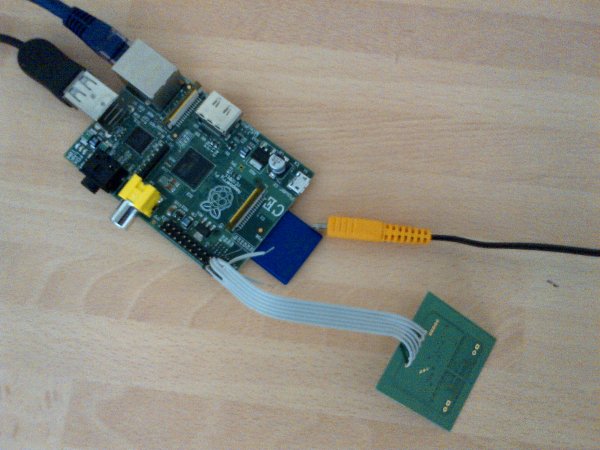
This is pretty simple so I won't spend too long on it… I got to draw and take a picture ;-).
One thing to note (if you look in the source code for the driver) the GPIO ports are configured for you and by default (as with most microcontrollers) are inputs. These are pulled high already (as per the I2C specification) with 1K8 pullup resistors. All this means the only thing you need to do is connect up the SL030 by matching up the letters on the pins.
Kernel Compile and Install
As many people have a tutorial on this I will not bother to recreate it, I just wish to thank Chris Boot, selsinork and everybody who contributes to eLinux.
# Stuff here to help my poor struggling brain crossdev -S -v -t armv6j-hardfloat-linux-gnueabi git clone –depth 1 git://github.com/selsinork/linux.git # from kernel directory cp arch/arm/configs/bcmrpi_cutdown_defconfig .config make ARCH=arm CROSS_COMPILE=armv6j-hardfloat-linux-gnueabi- oldconfig make ARCH=arm modules_install INSTALL_MOD_PATH=/tmp/modules
Incase it was not obvious I used selsinork's kernel 😉
Talking to SL030 via I2C
Once the Kernel was compiled I had my circuit all set up and wrote a nice bit of C and tried to get the firmware version number from the device. It should be:
0b f0 00 53 4c 30 33 30 2d 33 2e 32
 According to the datasheet… what I got was not that, the first byte seemed to be fine but all subsequent bytes had the MSB set so I kept getting this:
0b f0 80 d3 cc b0 b3 b0 ad b3 ae b5
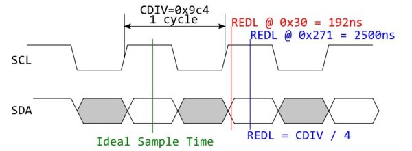
Too coincidental to be rubbish coming back from the device, the only thing I could think was that the Raspberry Pi clock was too fast… but then why are all the other bits of each byte correct? The Pi also says that it is running at 100KHz which is well within the tolerance of the SL030 which says 0-400KHz.
For more detail: Interface I2C with the Raspberry Pi